


Our Advice When Setting Up Mach4 with ESS and J Tech Lasers
 We have been getting requests to make a page on how to set up Mach4 for J Tech Lasers, as it is a bit confusing on the website on how to get the laser set up. So, we have answered the call and have set up Mach4 on our lab machine and want to share how to get it done for everyone. Let’s get started!
Equipment needed:
- Ethernet Smooth Stepper Control Board – This is the control board you need to run Mach4. Our instructions for the laser will only work with this board. You can get details for it here: https://warp9td.com/
- Breakout Board for the Smooth Stepper – We made our own so we know it is correct. You can get it here: https://jtechphotonics.com/?product=idc26_breakout
- Mach4 Software – Get it here: https://www.machsupport.com/software/mach4/
- J Tech Laser – If you have a mach4 machine, then try the Generic Bundle here: https://jtechphotonics.com/?product=generic-all-in-one-laser-and-mounting-kit-bundle
Electrical Hook Up:
We used Port 3 as our outputs from the breakout board to control the laser. We used Port 3, Pin 16 for the Laser PWM signal and the GND pin for the Ground Signal. Connect this to the laser driver input H4 or H2 port on the back of the driver.
Connect the ribbon cable from the ESS port 3 to the J Tech IDC 26 Breakout Board
Connect Ribbon Cable to ESS Port 3:


Take the 3′ mini Molex cable with the black Molex connector and the other end with bare wires and hook it up to the breakout board. Connect the red wire to Pin 16 and the black wire to GND on the breakout board.

Plug the input cable into the port H4 on the laser driver.
Software Setup:
If you already have Mach4 set up for your router or milling machine, then you can copy a profile that is already working and then modify it for the laser. In our case, we had to set up a complete machine from scratch to get it to work. We went through the Warp9 instructions to get the basic machine up and running. We are assuming you either already have a machine profile set up, or you can follow the instructions on the Warp9 page to get this far.
If you don’t have a profile set up yet, then instructions for setting up your profile in Mach4:
https://warp9td.com/index.php/gettingstarted/setting-up-the-smoothstepper-and-mach4
Now that you have your machine configured, then you can start your profile and we will go through how to set up the laser portion of the machine. These instructions are taking from here and modified a bit for our specific machine:
https://warp9td.com/index.php/faq/faq-mach4#LaserSetup

Once the loader is open, clone your working profile for your CNC by clicking the “copy profile” button. You can then name the new profile “J Tech Laser”. Never modify your working CNC profile.
We are going to be setting up two modes for the laser:
- Vector Mode – This will be for toolpaths with vectors in them that you create using a program like Vectric Aspire, V Carve, or Cut2D using a post processor.
- Rastor Mode – This will be for engraving images with Mach4.
Setting Up The Configuration:
1. To set up a Laser, go to Mach4 Menu -> Configure ->Control..>(was Mach4) -> Plugins.

Make sure that the Core, LUA, Regfile and ESS plugins are enabled.

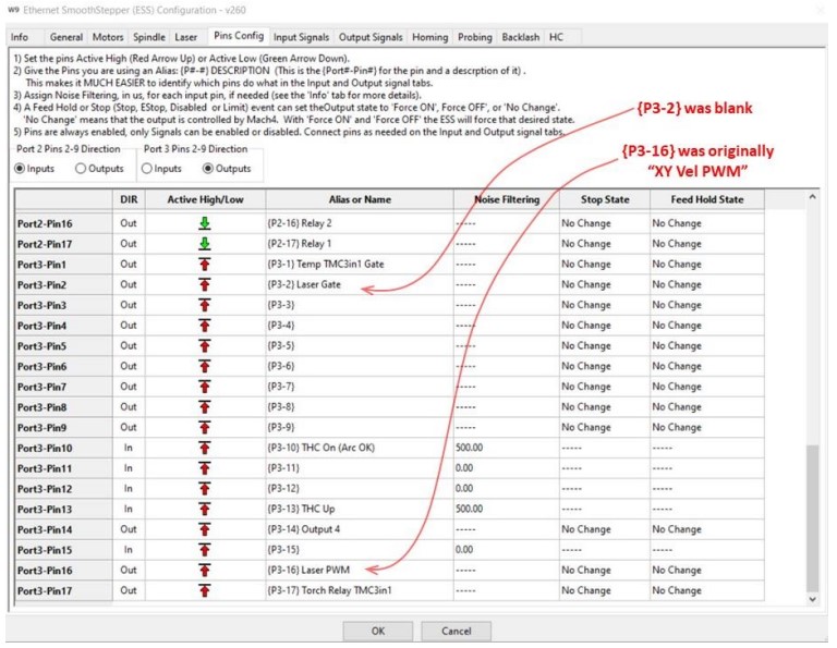
2. Now, go to Mach4 Menu -> Configure ->Plugins… -> ESS ### -> Pins Config Tab:
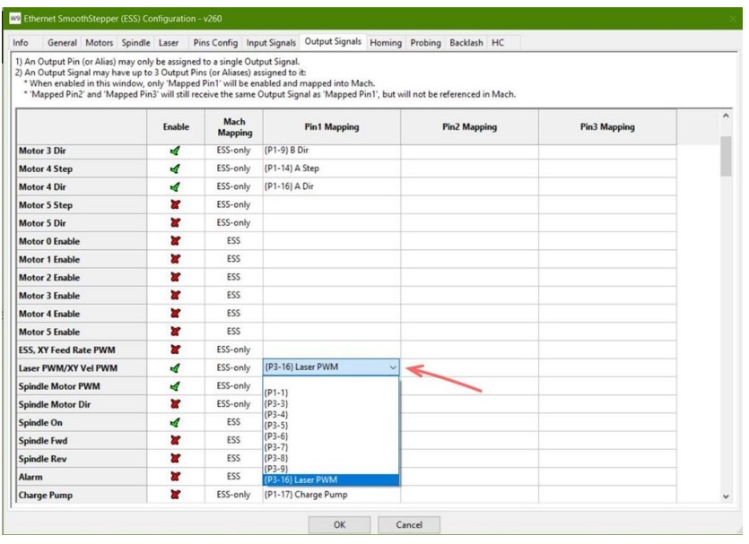
- Determine which output pin will be your Laser PWM output pin (I picked Port 3- Pin 16).
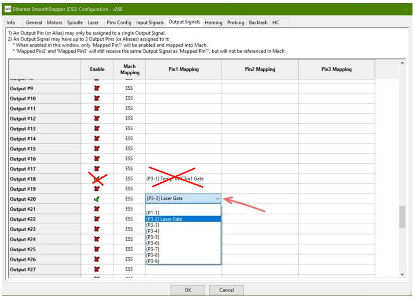
- Determine which output pin will be your Laser Gate output pin (I picked Port 3-Pin 2).
Now click over to the HC tab. In 1) set it to disabled. Uncheck the torch relay box in 3) and uncheck the box in 4) and the drop down should be “_”.

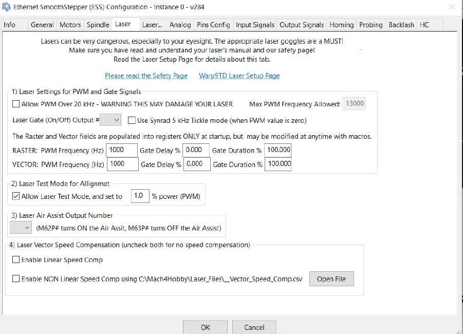
In the first laser tab, set your Laser Test Mode to a percentage that is low for your laser. We have it at 1% here, but you might have a different number. This is only if you chose the laser screen set.
In the second laser tab, make sure you have the “laser gate signal gates laser PWM for diodes” checked.
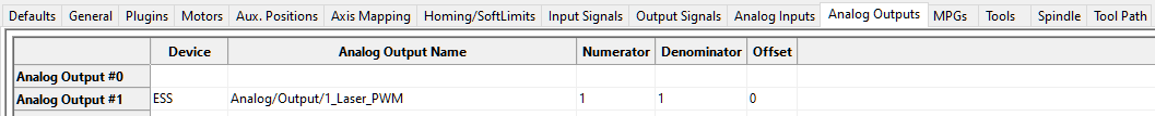
f you are running a new version with analog outputs, then you need to also click on the Analog output tab. Click on the analog output tab and make sure to copy the following.
After this, close down Mach4 and restart to get the changes to take effect.
Raster Mode
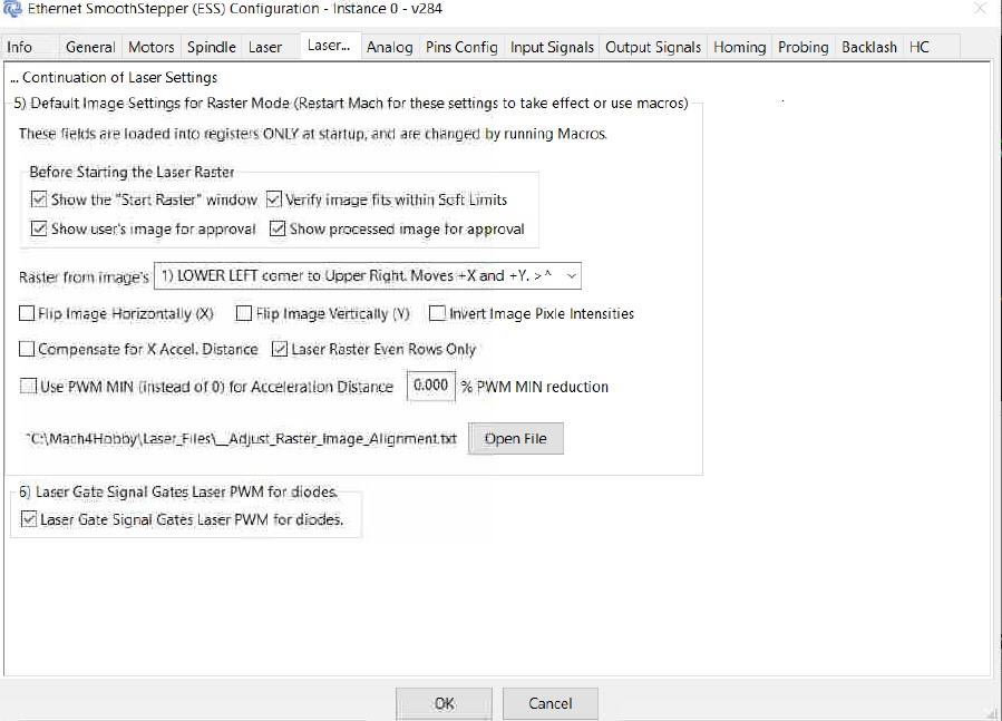
For the Raster Mode settings, you might need to change these when doing pictures. Mostly, it would be the flipping of the image. Keep these not selected unless you run into a situation where you might need them.
- Depending on the starting corner of your image, you may need to check “Flip Image Horizontally” to get the orientation and lettering to appear correct. This will flip or mirror your image left to right.
- Depending on the starting corner of your image, you may need to check “Flip Image Vertically”to get the orientation and lettering to appear correct. This will flip or mirror your image top to bottom.
- In an image, pure white (or the pixel value of 255) will burn with full intensity, and pure black (or the pixel value of 0) will not burn at all. To switch this, check “Invert Image Intensities”.
- “Compensate for X Acceleration Distance” means that the plugin will calculate the distance it takes to get up to the commanded velocity, which is where the pixels will be burned. The plugin will automatically move in the opposite direction before it starts to burn the first line of the image, so that the first image pixel will occur at the starting point of the Laser Raster. If you are using the “_Laser_Raster_Velocities.txt” file to manually adjust the Pre-Comp offset, that will be in addition to this automatically calculated value.
- If “Skip the Laser Raster Start Window” is unchecked, you will be prompted with a confirmation window before the Laser Raster Starts. Check this, if you do not want to see the confirmation window.
- “Laser Raster Even Rows Only” may be checked, and then only the Even Numbered rows (all in the same direction) will be burned. This is useful if you wish to check the overlap distance of your laser beam, or if you are having alignment issues with your Odd Numbered rows (i.e. a single vertical line is being rastered as two vertical lines – in this case, you would need to adjust your Motor Delay Distance).
Running J Tech Lasers with Mach4
Now you have the setup all done, let’s go through a project really quickly.
We are going to do this in Vectric Using the J Tech Mach4 post processor. You can get it here:
If you have the Vectric Laser Module, then you can get the post processor here:
You need to install the post processor for the laser into Vectric. For help on how to do this, we have a video here:
Here is an example with the “non-laser module” post processor
Create your text in Vectric and then select the quick engrave toolpath.

Select your tool. We used a 7W with a high res lens. Your spindle speed will be your Laser Power in Percentage form. It will be from 0% to 97%. *NOTE* There is a glitch that only allows 0 to 97% power. If you put over 97%, then the laser won’t fire at all. Choose between 0 and 97 for laser power.

Choose your vectors and calculate the toolpath.

Choose your “J Tech Laser Mach4 Vector – No Z (inch)” post processor from the list. Press “Save Toolpath” and save it to your computer.

Open up Mach4 and press the “load G Code” button. Choose your file.

Press the “Enable” button to enable the machine. Then press the “Cycle Start” button to start the engraving. Make sure you are at your zero point.

It should now run and engrave your text. You can do more advanced engravings by using fills and the other features of the Vectric products.
Picture Engraving
Picture engraving in Mach4 is not a simple process. I recommend that you try the demo before you jump into purchasing a Mach4 machine license to see if you can hack doing pictures. There are a lot of settings you need to get correct, including your image file and your configuration. If you have any of them wrong, it will not work. Enough for the disclaimer, let’s try this out!
- You will need to have a directory with your pictures you want to engrave as well as a G Code file you edit to start your engraving. Let’s start by making a folder for your pictures.
We made a folder on the C:\ drive labeled “pictures”.

In order to start a laser image process, you need to create a small G Code file. It will have the parameters in it for the image to be processed. Once you get all of the settings correct, you can then just change the name of the image in the file to run. Here are the lua script commands used to set up the Laser Raster: 1. m2000 (C:\Pictures\image.bmp) This command will look for the image.bmp picture in your C drive. You can point to any folder location you wish, and use any image name that you wish. The requirement is that the image be a 256 color (8 bit) gray scale bitmap or a 24 bit RGB bitmap without an alpha channel. 2. m2001 (Comment)
- m2001 (UNITS=IN) This will tell the software that all your commanded values will be in Inches. This must be the same as the default units for your profile in Mach4’s General Tab for Machine Setup Units. If your default units are metric, you must call m2001 (UNITS=MM) for the software to run.
- m2001 (FEEDRATE=900.9) you may specify your desired feedrate. However for Build 221, it will be ignored and the appropriate, calculated, feedrate will be used.
- m2001 (IMAGE_STARTING_CORNER=#) The Laser Raster will start from the commanded corner and work to the opposite corner. Replace the # with 1, 2, 3 or 4. 1 means start from the Lower Left corner of the image. 2 means start from the Lower Right corner of the image. 3 means start from the Upper Right corner of the image. 4 means start from the Upper Left corner of the image.
- m2001 (IMAGE_COLOR_CHANNEL= #) If you are using a 256 color gray scale image, this command is not important. If you are using an 24 bit RGB image, this command allows you to select which color channel the image data will be taken from. 1 means the Red color channel.2 means the Green color channel. 3 means the Blue color channel. 4 means the average of all three color channels.
- m2001 (IMAGE_INVERT_INTENSITIES=0) 0 Means that pure white (or the pixel value of 255) will burn with full intensity, and pure black (or the pixel value of 0) will not burn at all. 1 means that pure black (or the pixel value of 0) will burn with full intensity, and pure white (or the pixel value of 255) will not burn at all. This will override the default setting in the Laser tab for “Invert Image Intensities”.
- m2001 (IMAGE_FLIP_X=0) Depending on the starting corner of your image, you may need to set this to 1 to get the orientation and lettering to appear correct, by flipping or mirroring your image left to right. This will override the default setting in the Laser tab for “Flip Image Horizontally”.
- m2001 (IMAGE_FLIP_Y=0) Depending on the starting corner of your image, you may need to set this to 1 to get the orientation and lettering to appear correct, by flipping or mirroring your image top to bottom. This will override the default setting in the Laser tab for “Flip Image Vertically”.
- m2001 (PWM_MAX=100) This will set the Maximum PWM Duty Cycle corresponding to a pixel intensity value of 255 (full burn value). Depending on the speed of the raster, a 100% value may be too high.
- m2001 (PWM_MIN=15) This will set the Minimum PWM Duty Cycle corresponding to a pixel intensity value of 0 (no burn value). Depending on the speed of the raster, a 0% value may be too low. This is ideally set just low enough that it does not burn the surface of the material, but a pixel value of 1 will.
- m2001 (SHOW_WINDOW_TO_START=1) When set to 1, you will be prompted with a confirmation window before the Laser Raster Starts. Set this to 0 if you do not want to see the confirmation window. This will override the default setting in the Laser tab for “Skip the Laser Raster Start Window”.
3. m2002 (This starts the Laser Raster) This will tell the software to start the laser raster process. When the laser raster process starts, a log file is created and updated at “C:\Mach4Hobby\Plugins\_PROCESSING LASER COMMANDS LOG.txt“. This file will explain what is happening and what, if anything, went wrong. This is very useful to see if your settings are incorrect. For an example, warp9 has a test file and program you can run.
Here are the files to run this: Shield.nc File DownloadShield.BMP Download
Here is the G Code file explained:
G90 G00 X1.0500 Y1.9465 M2000
(C:\Pictures\Shield.BMP)
M2001(UNITS = in)
M2001(FEEDRATE = 10.000000)
M2001(IMAGE_STARTING_CORNER = 1)
M2001(IMAGE_COLOR_CHANNEL = 1)
M2001(IMAGE_INVERT_INTENSITIES = 0)
M2001(IMAGE_FLIP_X = 0)
M2001(IMAGE_FLIP_Y = 0)
M2001(MOTOR_DELAY_DISTANCE_X = 0.0)
M2001(PWM_MAX = 90)
M2001(PWM_Min = 5)
M2001(PWM_ZERO = 0)
M2001(SHOW_WINDOW_TO_START = 1)
M2001(SHOW_IMAGE_CORNER_POSITIONS = 0)
M2002(This starts the Laser Raster)
G4P1 (Wait here while the Raster happens)
M2003 (LASER_VECTOR_PWM_PERCENTAGE=76.00)
M2003 (LASER_VECTOR_FREQUENCY=1000)
M2004 G00 X1.0010 Y1.9990
M62 P20 G01 X1.9990 F90
G01 Y1.0010 G01 X1.0010
G01 Y1.9990
M63 P20
M2005 M9
G00 X0 Y0 M02
Note, you can change the initial offset, the feedrate, and the corner where you start. Try messing around with this in the file and see how you like to engrave your pictures. Once you have it set, then load into Mach4 and press Cycle Start. You will get a pop up telling you the speed at which it will engrave. Press Yes to continue.
The picture should start engraving after this.
Running New Picture Files
Now that you have the example from the shield image, you can run new pictures by just changing the name of the image in the file. Here is how to make your new image and format it correctly to work. We recommenced using the photo editing software that Warp9 recomends as well. It is called GIMP and it is free and open source. Here is the download link: DOWNLOAD GIMP PHOTO EDITING SOFTWARE Load your color image into the program. You can use the “Scale Image” to make it a size you want. Adjust the resolution and the size to match what you want to engrave. Then press the “export as” to save the image.

Click on the “select by file type”

Then select the Windows BMP format and press Export.

Make sure you check the “do not write color space information” in the compatibility options. Check the “R8 G8 B8” in the advanced options. Then Export the image by clicking Export.

We put the image into the pictures folder and changed the path name to the name of the image we just exported. This line would be this for the image: M2000 (C:\Pictures\PorscheColor.BMP) Now try your own pictures and start to play! If you run into issues, Warp9 discusses how to do line alignment if your axis are off in the rastor. Here is from their website:
Laser Raster Line Alignment
For Laser Rastering, each row starts by accelerating up to the commanded velocity (feed rate) at which point the SmoothStepper will start issuing the PWM values for each pixel. Once all of the pixel data for the row has been used (over the distance commanded for the row in the image), the X axis motion then decelerates to a stop so the Y line distance can be moved before the next row is rastered in the opposite direction. If you motors or axes have lag (this could even be just a little backlash pullout) you will have a horizontal offset in your rastered image. You can easily see if this is the issue by selecting the option in the Laser tab for “Laser Raster Even Rows Only”, and the alignment issue will be gone on your next image. Please make sure you uncheck this option after you have verified that this is the issue. To fix this issue, you will need to adjust your “Motor Delay Distance” in C:\Mach4Hobby\Plugins\_Laser_Raster_Velocities.txt Your delay distance will need to be essentially 50% of the distance you are off by in your original alignment at that velocity or feed rate. The faster your feed rate, the larger your Motor Delay distance will need to be. It is best to enter specific distance values for all of your common feed rates, but the software will interpolate the distance based off of higher and lower values. Once these changes have been made your image should be in perfect alignment. More information regarding the setup is inside the “_Laser_Raster_Velocities.txt” file itself. Please make sure to include one or two distance lines for feed rates faster than you expect to use so you are covered on the high end if you forget. First try with Laser Raster Line Alignment Issues

Second and Third tries with Laser Raster Line Alignment Issues, and success on the Fourth attempt.

The image above shows that the alignment was corrected with the proper motor delay distance. However, the quality of the image still suffers a little bit due to insufficient resolution; increasing the DPI would help to improve the quality of the image.
Hi,
A newbie question – is it possible to use Lightburn following this setup for Mach4? If so which controller should be chosen to set it up.
Many thanks for this article it is very helpful.
Pau
I have followed this and downloaded the shield as well. I can get the laser to fire and work in vector mode with pwm. But it won’t fire at all when I’m trying the raster mode of the shield bitmap. It runs the file, but the laser never turns on. Changing the min pwm doesn’t get it to turn on either