

 The folks over at Legacy Woodworking Machinery put out a great product with the Maverick CNC. The table size is amazing and it comes complete with a turning station! The only thing it is missing is a laser. So let’s see how we can add one to make this one of the most versatile machines on the market!

The Maverick Machine
Customer Video
Floyd Gibson from California has made a nice video showing his installation of his J Tech 7W laser on his Maveric machine. He constructed a plate to mount the generic magnet mount to the front of his spindle and mounted the driver to the back panel. We will discuss the details on this page, but here it is in action.
What to Order?
We have made this easier to order your laser for the Legacy system with the Generic All In One Laser and Mounting Bundle. It will have everything you need to get started on your upgrade. Most people go for the largest power laser (more power means better speeds for engraving), the magnetic shroud version (shown below) for added safety, and also the High Resolution lens option for engraving in fine detail (down to 0.06″ in some cases). You will NEED to get the 10′ extension cord option. 5′ might work, but it is good to have a bit extra just in case.
Click on the links for the order page:
Generic All In One Laser and Mounting Bundle


Mounting the Laser
Once you get your laser, you are going to need to mount it. If you purchased the magnetic shroud, it will come with the base plate that you will need to mount so the laser can get to 1/8″ from the bottom of the shroud and the work surface. This means you will need to fixture the laser base plate so the laser will be able to go down to the work at this level. We recommend putting the laser either in front of the spindle or on the side. You can utilize the existing bolts for the spindle holder to make a removable plate with the laser on it or you could drill and tap some holes in the aluminum spindle holder for the laser base plate.

Mark Detert was happy to share his installation with us. He made a custom plate for the front of the machine and drilled and tapped some holes to mount it. Here are the pictures:

Fabricate a plate for the laser mount
Drill and tap the holes\
Square the plate
Attach the magnet base plate and the laser
The details for the laser size are located here on the documentation page:
You will need to decide if you want to mount just the laser or to mount both the laser and the laser driver to the spindle holder. In the case of mounting just the laser, you will need to get a short extension for the laser and fan to reach back to the electronics cabinet where the laser driver will be mounted. They are available here:
Connecting the Laser Driver
The electronics for the machine are located inside the gantry, which will make the process of connecting the laser driver a bit easier than if it was off the machine.
First, remove the screws on the back gantry plate to get into the electronics enclosure:

Pull of both of the back electronics enclosure panels to expose all of the electronics.
The Smooth Stepper Breakout board is the board that has the blue screw terminals on it. We will be connecting the laser driver Mini Fit Jr. input cable to this board.
There will be a small mini molex cable with a Black mini fit jr connector on one end and bare wires on the other. You can see the cable labeled “mini fit jr input cable” in the picture below:
On the back of the black laser driver, connect the Molex Mini Fit Jr input cable from Terminal H4 to:
Pin 17 : Laser Driver Red Positive Wire
GND: Laser Driver Black Negative Wire

There should be room to mount the laser driver in the enclosure on the back plate. Just find a suitable space for it and mount it. An example is show here of Marks install.

You can also mount the driver to the outside of the panel to allow for access to the keys and power switch.

Setting Up Mach3
First thing to do is to make a copy of your current mach3 profile so you don’t mess up your working machine configuration. You can simply go into the mach3 folder and copy the XML file and then name the new file something like “laser”. When you load mach3, you can then select the laser profile and start modifying it.
We are going to configure the laser for simple “ON” and “OFF” control. To start, open up the “Ports and Pins” menu by clicking “Config” -> “Ports and Pins”.
To get the spindle to just turn on and off, ignore the spindle set-up in the “Motor Outputs” tab for now. Instead, we are going to configure it just as a standard output. The first thing to do is enable an output and map the pin on the parallel port to the software. Go to the “Output Signals” tab:
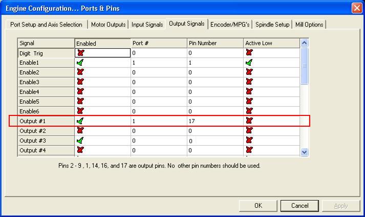
In the “Output Signals” tab, put a 1 in the “Port #” box and a 17 in the “Pin Number” box. This will enable the output (green checkmark next to it) and map it to Pin 17 on the blue breakout board.
Now go to the “Spindle Setup” tab:
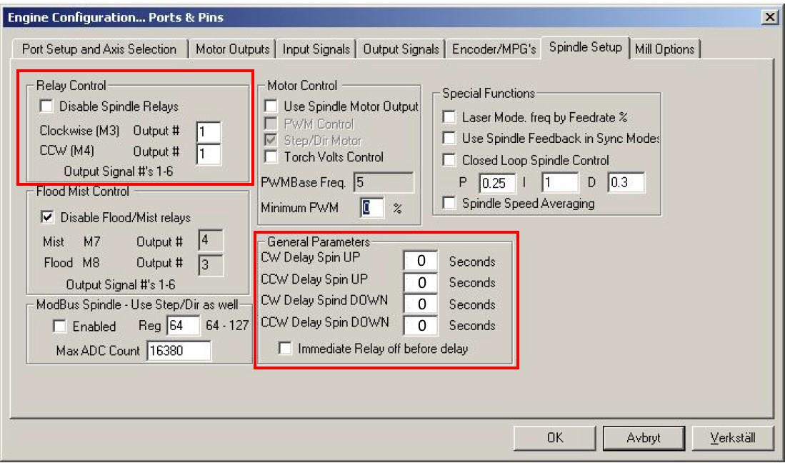
In the top left corner, uncheck the “Disable Spindle Relays” box and put a 1 in both of the “Clockwise” and “CCW” boxes. Since we just mapped the output #1 to pin 17 in the last step, whenever a M3 (clockwise) or a M4 (CCW) command is sent in G Code, it will now enable output #1 (pin 17).
So, the M Code to turn on and off the laser now is:
- Laser ON: Either “M3” or “M4”
- Laser OFF: “M5”
In the “General Parameters” section, change all of the delays to “0” seconds. They will default to a “1”, which will leave a mark on your object you are engraving because it will pause for a second.
Setting Up Mach3 with Minimized Delay
If you are having issues with a delay, then it might be better to use the M10p1 and M11p1 commands.
A way to get around this problem is to use the M code to turn on an output instantaneously. These commands are:
- M11p# – Turn on the output the laser is on, where # is the number of the output.
- M10p# – Turn off the output the laser is on, where # is the number of the output.
So, if your output is set to 1 the command to turn on the laser is now M11p1. To turn it off it is M10p1. The post on the machsupport forum about this is here: http://www.machsupport.com/forum/index.php?action=printpage;topic=23636.0
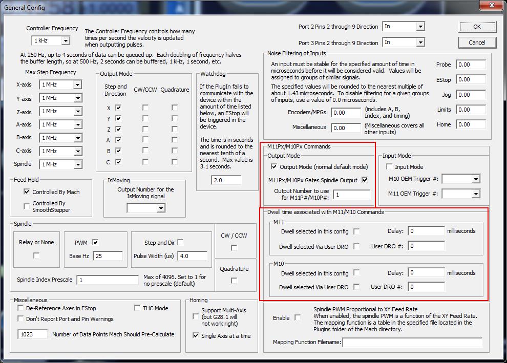
***If you are using the Ethernet Smooth Stepper you will also need to set the output in the “General Config” page on the ESS plugin. In this example it is set to output #1. Also, turn off any dwell associated with this output method by unchecking the boxes in the dwell section.
Software
We recommend using Vectric Software with your laser. You can download and set up the post processor by following the instructions on this page:
You will either choose the “Mach3” post processor or the “MACH 3 – M11p1/M10p1 option” post processor depending on how you set up your output in the last step.
That is it!
Buy your laser upgrade kit now!
Remember Safety First!

We sell laser shielding to block laser radiation and reflections!
Laser Goggles are also a must!
Disclaimer
The laser used in this project is very powerful and all safety precautions must be taken. Use proper safety eyewear to prevent injury to eyes. This is a project and J Tech Photonics, Inc. is not responsible or liable for any and all damage or injury caused to people or property. The use of these instructions to make a laser cutter is under your own discretion and all safety precautions should be followed. J Tech Photonics, Inc. is not affiliated in any way with Legacy Woodworking Machinery and they may change hardware and software at any time making these instructions invalid.