

![]()
Reliable Ultimaker 1 & 2 Laser Upgrade Implementation
Ultimaker is a very popular open source printer, with a large print platform and great accuracy, it makes for an even better laser engraver! These are the details on how to upgrade the Ultimaker printer to become a cool laser engraver with any of the laser upgrade kits.
This is the basic integration of the electronics to get the laser driver controlled by the Ultimaker with commands in G Code. Of course, you will need to print out a mechanical mount for the laser as well. The dimensions and solid models are located in the documents section of the website.
The Ultimaker 1 we are looking at to upgrade has the V1.5.7 version of the electronics board located here: http://reprap.org/wiki/Ultimaker%27s_v1.5.7_PCB using the Marlin version of the firmware located here: https://github.com/Ultimaker/Ultimaker2Marlin/tree/master/Marlin
The Ultimaker 2 has a version 2.1.1 of the electronics board and the files are available at GitHub via open source here: Main%20Board%20V2.1.1.pdf It will also use the Marlin version of the firmware from above.
So, let’s get started! There are two different ways to hook up the laser driver to the Ultimaker board. One uses the PWM output for the Fan and the other uses another PWM output for an LED. Either one will work, it just depends on which way you want to go.
Upgrading Ultimaker 1
Method 1: Using the PWM output for the FAN for Ultimaker 1
If you are not already using this for an additional fan on your Ultimaker, then this might be the easiest way to go for you. The fan control on the Ultimaker Board is pin 7. On the board it is a standard Molex connector on the top middle of the board labeled “PWM”. If you don’t have a fan attached, simply connect the “+” to the laser input “+” and the “-” to the laser input “-“. You then control it in G Code with M106 SXXX command where XXX is a value between 0 and 255. Then use M107 to turn the laser off. You can get the connector here at the shop or find it on your own.
Here are pictures of the board showing the FAN option location.
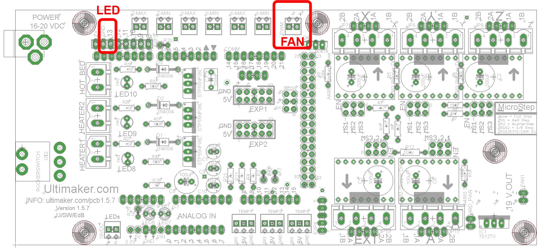
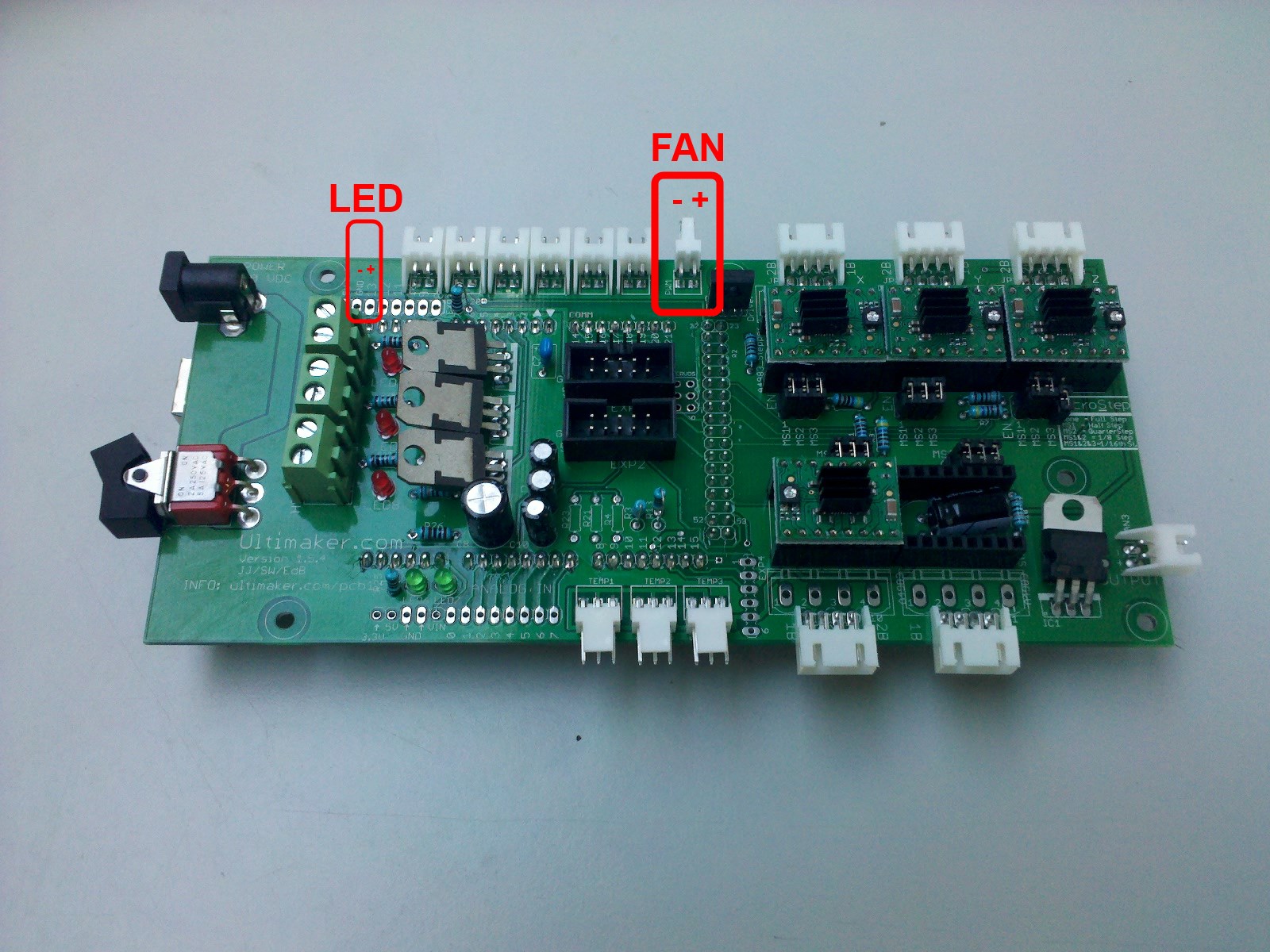
Method 2: Using the PWM output for the LED for Ultimaker 1
Ultimaker added a cool upgrade to be able to put an LED in the printer to be able to see better and just for a cool factor. The neat thing is that they also have a provision to control this output as well.
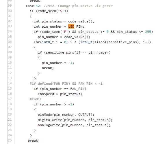
Looking at the board, it is in EXP3, pin number 13. You can solder a wire to this pin for the “+” signal and then solder a wire to the “GND” pin next to it for the “-” signal for the laser control. You then control it in G Code with M42 P13 SXXX where XXX is a value between 0 and 255. Use M42 P13 S0 to turn the laser off. If you want to have the laser all the way on, then it is “M42 P13 S255”. For 50% power it is “M42 P13 S127” and so on.
The pictures above also show the placement of P13on the left side of the board. Here are the details of the firmware showing this implementation:
Upgrading Ultimaker 2
Mechanical
Kudos to Wisar for sharing his mount he made for his J Tech laser on his Ultimaker 2! It maximizes the print area and has a very good mount for the fan. You can print it out at the thingiverse page right HERE.

Or you can download them here on our site:
Electrical
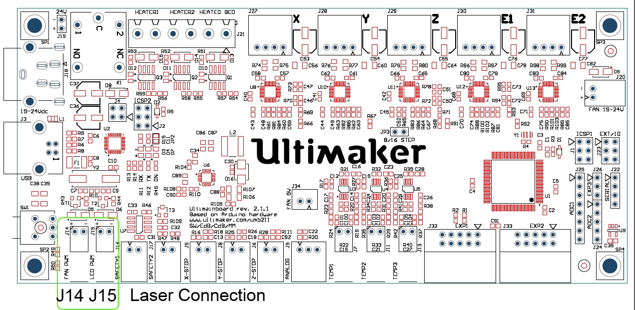
You again have the same choice of which way you want to upgrade, either using the fan or the led output on the board. The new 2.1.1 main Ultimaker board is even EASIER than the previous version. Now they put in two nice Molex connectors so you don’t need to do any messy soldering to get to your signals! You can get the connector here at the shop or find it on your own. To control the laser it is the same as the Ultimaker 1 version.
Using Fan J14: Control it in G Code with M106 SXXX command where XXX is a value between 0 and 255. Then use M107 to turn the laser off.
Using LED J15: Control it in G Code with M42 P13 SXXX where XXX is a value between 0 and 255. Use M42 P13 S0 to turn the laser off.

Using the FAN Connection firmware mod
When using some versions of firmware, there will be a “kickstart” for the fan that creates a burst of power in the beginning. This will cause the laser to make a spike in the begining of the run and leave a dot in the material. To remove this feature, you need to do a quick modification of the firmware.
From the Ultimaker users forum:
In Configuration_adv.h look for this:
// When first starting the main fan, run it at full speed for the
// given number of milliseconds. This gets the fan spinning reliably
// before setting a PWM value. (Does not work with software PWM for fan on Sanguinololu)
#define FAN_KICKSTART_TIME 200
#define FAN_KICKSTART_MINPWM 20
Now, just set the time to 0 or minpwm to 255. Change it to this:
// When first starting the main fan, run it at full speed for the
// given number of milliseconds. This gets the fan spinning reliably
// before setting a PWM value. (Does not work with software PWM for fan on Sanguinololu)
#define FAN_KICKSTART_TIME 0
#define FAN_KICKSTART_MINPWM 255
This will remove the “flash” the laser will produce when using the fan output and everything will work correctly.
Buy your laser upgrade kit now!

Remember Safety First!

We sell laser shielding to block laser radiation and reflections!
Laser Goggles are also a must!
Disclaimer
The laser used in this project is very powerful and all safety precautions must be taken. Use proper safety eyewear to prevent injury to eyes. This is a project and J Tech Photonics, Inc. is not responsible or liable for any and all damage or injury caused to people or property. The use of these instructions to make a laser cutter is under your own discretion and all safety precautions should be followed. J Tech Photonics, Inc. is not affiliated in any way with Ultimaker and they may change hardware and software at any time making these instructions invalid.