

MACH 3 is a very popular software package for CNC machines that enables motion control on a normal computer via a parallel port without the need for fancy extra controller boards running motion control applications. This simplifies the interface boards and allows for many manufacturers to make custom widgets.
We get a lot of questions every day on whether our upgrade kits work with MACH3. The answer is a simple YES! But the details behind it depend on the interface board you buy from a third party. There are plenty of outputs on MACH3 that you can use to control the laser and every interface board we have seen implements at least one of these outputs.
***NEW UPDATE****
Many people are asking for an easier way to set-up the laser with MACH3. We have just introduced a new way to connect the laser using a “pass through” DB25 break out board. Check out the section under Hardware Overview.
Hardware Overview
The implementation is pretty simple, but first we need to understand the details of what is going on behind the scenes. Basically you have four things in the picture in terms of hardware:
- A computer running MACH3 software with a parallel port.
- An interface board with terminals for motors, inputs, and outputs.
- J Tech Photonics laser driver board.
- J Tech Photonics laser.
The computer connects to the interface board, the interface board to the laser driver board, and then to the laser.
Computer -> Interface Board -> Laser Driver -> Laser!
The end goal is to be able to turn on and off the laser with G Code in software on the computer. Here is an example of a TB6560 4axis controller board with MACH3 connecting a laser:
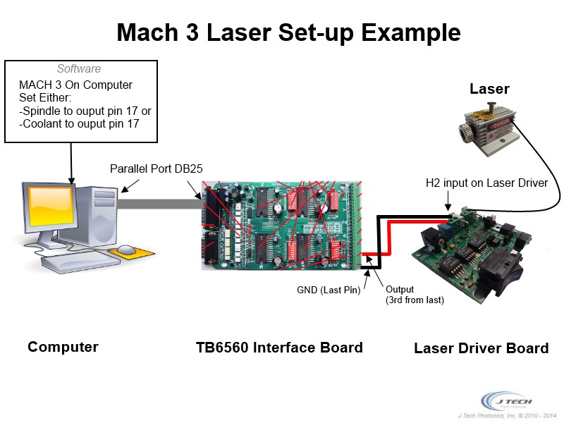
If you have other controller/interface boards, it is pretty similar. Look at the manual and find where they have their outputs and connect to the appropriate one.
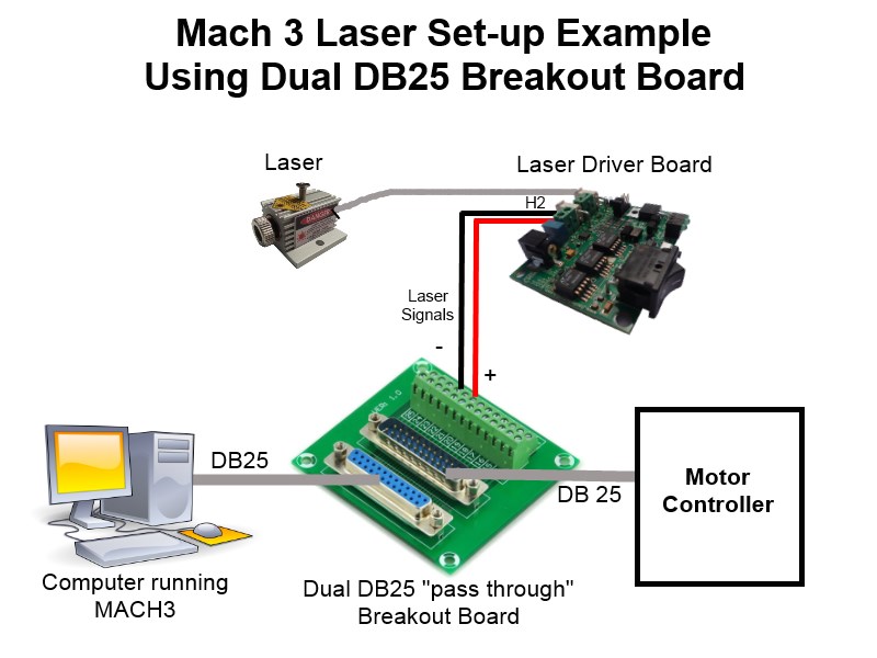
Hardware Overview Using DB25 Dual Breakout Board
Many motor controllers for use with MACH3 have poor documentation or the outputs just do not work correctly. So, to get around this problem we are now offering a DB25 Dual Breakout Board to get the signals directly from MACH3 and not the controller. All of the needed signals for the motors are still passed through to the computer, but the signals the laser needs are plucked from the cable using the breakout board and terminal strips. Choose a positive output for the red wire (like pin 17 or pin 1) and a Ground for the black wire (pin 18 through pin 25 are ground- we normally use pin 18). It is all set-up like this now:
Software
Now that you have your hardware connected, how do I get the laser to turn on and off with a G Code program? That is a good question! You will need to configure your MACH3 software to tell it which output will be the laser. In this, there are three ways to go. You can either make the laser a Spindle, make the laser a Coolant, or write you own custom VB script and make the laser whatever output you want. We will cover the first two options here.
Which way to choose, Spindle or Coolant?
Well, if you already have everything all set up for your machine and you don’t want to mess with changing the spindle connections and outputs you already have, maybe the Coolant is the way to go. The Spindle option however has the built in ability to control via PWM! Yes, that’s right, you can have power control built right into the MACH 3 software. The other good news is that MACH3 supports multiple machine configurations, so you can make a new one and call it “Laser” and build a completely spindleless configuration. Also, many G Code translation programs already output in terms of M3 and M5 commands for the spindle start and stop, so you won’t have to change anything in the G Code if you go with Spindle.
Spindle as Laser
If you have chosen Spindle, you will have two options to choose from to control the laser. You can either just turn it on and off or you can turn it on with PWM and turn it off. We will first through the just simple “On” and “Off” first. To start, open up the “Ports and Pins” menu by clicking “Config” -> “Ports and Pins”.
To get the spindle to just turn on and off, ignore the spindle set-up in the “Motor Outputs” tab for now. Instead, we are going to configure it just as a standard output. The first thing to do is enable an output and map the pin on the parallel port to the software. Go to the “Output Signals” tab:
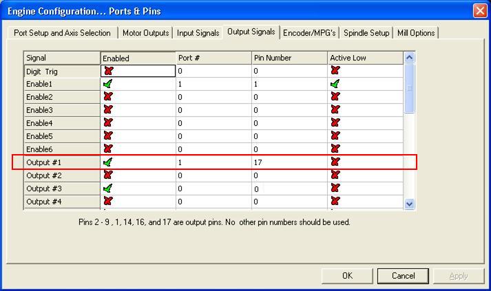
In the “Output Signals” tab, put a 1 in the “Port #” box and a 17 in the “Pin Number” box. This will enable the output (green checkmark next to it) and map it to Pin 17 of the DB25 connector. For the physical connection on your your red positive signal pin will be 17 and your ground negative pin will be pin 18 on a LPT breakout. Check your breakout board where you have your ground pin if not using a LPT cable.
Now go to the “Spindle Setup” tab:
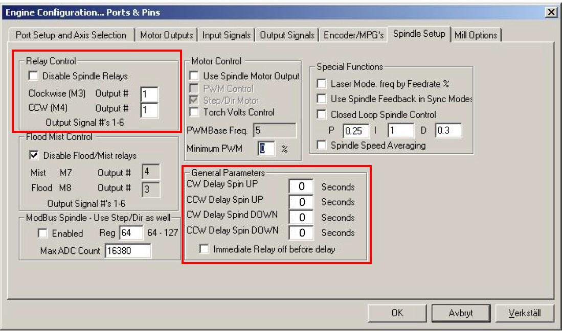
In the top left corner, uncheck the “Disable Spindle Relays” box and put a 1 in both of the “Clockwise” and “CCW” boxes. Since we just mapped the output #1 to pin 17 in the last step, whenever a M3 (clockwise) or a M4 (CCW) command is sent in G Code, it will now enable output #1 (pin 17).
So, the M Code to turn on and off the laser now is:
- Laser ON: Either “M3” or “M4”
- Laser OFF: “M5”
In the “General Parameters” section, change all of the delays to “0” seconds. They will default to a “1”, which will leave a mark on your object you are engraving because it will pause for a second. If you are still having issues with a delay, look at the last section in this article with a possible solution.
Coolant as Laser
So let’s say you don’t want to set up a whole other configuration for your machine, or you already have a spindle on the machine but not coolant and you don’t want to change anything. Well, adding the laser to the coolant output is just as easy as the last step with the spindle.
In the “Output Signals” tab, map the Output #1 to Port 1 and Pin 17. You can make this another output you want, just make sure you are consistent with the setup. Then in the “Spindle Setup” tab (see the last picture), uncheck the “Disable Flood/Mist Relays” and put a 1 in the “Mist” box and a 1 in the “Flood” box. This will now enable pin 17 whenever a M Code “M7” or “M8” is in the program.
To turn on and off the laser it will be:
- Laser ON: Either “M7” or “M8”
- Laser OFF: “M9”
Using Spindle PWM to Control Laser
Now this is a bit more advanced to do, but in the end you should have power control via PWM of the laser as well and the general On and Off signals from before.
The theory is that you want a specific frequency to run the laser at and then you can adjust the duty cycle to increase or decrease the power of the laser. It would be nice to adjust the power of the laser in easy 1% increments, so we will set it up that way.
We are first going to change the kernal frequency and the Spindle frequency.
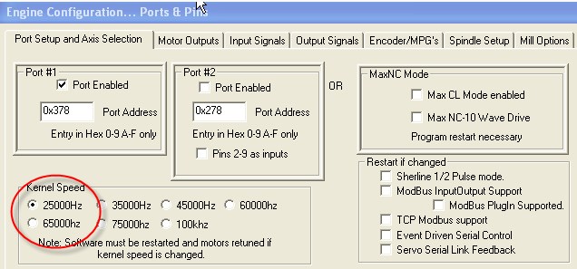
In the “Port Setup and Axis Selection” click the Kernal speed to 25000Hz.
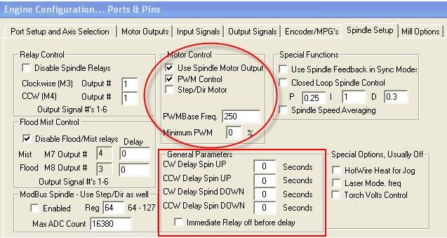
In the “Spindle Setup” tab, check Use “Spindle Motor Output” and “PWM Control”. Also set the base Freq. to “250” and the Minimum PWM to “0”. In the “General Parameters”, make sure all of the delays are set to Zero.
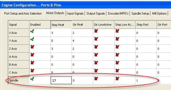 In the previous section, we used PIN 17 as our In the “Motor Outputs” tab, map the pins for the spindle to 17 and 0. Remember, this number is specific to your set-up and may require a different pin out. Just check in your instructions on which one it is. For example, if you used pin 1 for your output, then set your spindle step pin to 1.
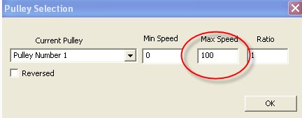
In the “Config” —> “Spindle Pullys” selection, enter “0” for Min Speed and “100” for Max Speed and a Ratio of “1”. This will then equate the spindle speed setting for laser power with a one to one ratio. Full power is 100 and off is 0 (or better to use M5).
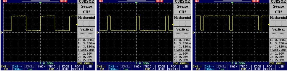
To control this new PWM output in G Code, simply add an “SXXX” command to the normal spindle M Code of M3 or M4 where the “XXX” is the power of the laser. Some examples of the code are:
- M3 S100 – Laser ON at full power
- M3 S90 – Laser ON at 90% power
- M3 S50 – Laser ON at 50% power
The image below shows different duty cycles for 50%, 10% and 90% respectively.
Picture Engraving with Mach3
Note that this PWM method normally produces a slight delay in each command. If you want to use the PicEngrave software, we have developed an encoder solution that will allow you to control a 4th axis to produce the commands needed to run full speed with picture engraving. This method was developed by Jeff and John at picengrave.com and uses the 4th axis step and direction signals to produce the PWM output needed to engrave pictures in 8bit resolution. The PicConvert™ board converts the step and direction outputs from mach3 into a PWM signal for the laser driver.
Setting up the board is not trivial, so we recomend you read the manual first before purchasing so you understand the details involved with getting it set up. The manual is located here:
Pic-Convert Manual V2_6
To purchase the PicConvert™ board go to the shop page here:
https://jtechphotonics.com/?product=dacpwm-converter-board

Solution to Possible Delay in Mach 3 using M3 and M5 Commands
Some customers are experiencing delays in the start of the laser when doing vector drawings due to the M3 and M5 commands being linked to axis move commands. A way to get around this problem is to use the M code to turn on an output instantaneously. These commands are:
- M11p# – Turn on the output the laser is on, where # is the number of the output.
- M10p# – Turn off the output the laser is on, where # is the number of the output.
So, if your output is set to 1 the command to turn on the laser is now M11p1. To turn it off it is M10p1. The post on the machsupport forum about this is here: http://www.machsupport.com/forum/index.php?action=printpage;topic=23636.0
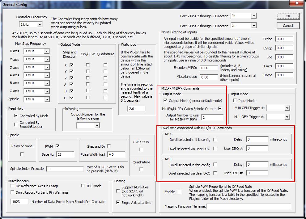
***If you are using the Ethernet Smooth Stepper you will also need to set the output in the “General Config” page on the ESS plugin. In this example it is set to output #1. Also, turn off any dwell associated with this output method by unchecking the boxes in the dwell section.
**Note this does not fix picture engraving. You still need the PicConvert™ board mentioned above for this**
Now you are all configured and ready to go with Mach3 and your laser from J Tech Photonics! Go on and create!
Buy your laser upgrade kit now!

Remember Safety First!

We sell laser shielding to block laser radiation and reflections!
Laser Goggles are also a must!
Disclaimer
The laser used in this project is very powerful and all safety precautions must be taken. Use proper safety eyewear to prevent injury to eyes. This is a project and J Tech Photonics, Inc. is not responsible or liable for any and all damage or injury caused to people or property. The use of these instructions to make a laser cutter is under your own discretion and all safety precautions should be followed. J Tech Photonics, Inc. is not affiliated in any way with MACH3 or ArtSoft and they may change the software at any time making these instructions invalid.
Quick note to Mach 3 users, on my CNC I use the M11p# and M10p# commands to turn the laser on and off (i.e; M11P17, M10P17). What was confusing was that the pin 17 didn’t instant respond UNTIL there was an axis movement (which is what you want!). This will make sure that the laser is off during travel moves and On during engraving.
I use Vectric Aspire for most of my CNC machine work and simply modified the post processor to ignore Z moves and provide the appropriate laser On/Off commands instead of using the Spindle On/Off.
Great post! Is there any update on controlling the laser with 4th axis step and dir signals?
Laser driver or Mach 3 issue or C10 breakout board w/ UC100.
Recently, my laser starts to fade to off at random times during a run and sometimes not even turning on at all. It turns on/off, no fading when using the input command in Mach 3 and stay on with ccw switch. I use vcarve pro post processor listed in this website and modified to use M3/4, M8/9 and mp10/11 and the all have the same results.
This set up has worked fine for a couple months so…
Thanks in advance for any suggestions.
I used this postprocessor with v8.5 and it worked great but when i went to vcarvev9 the vcarve program failed in mach 3 am i doing somithing wrong?
Hello, I’m using Mach3 with a Gryphon CNC MX4660 and have mounted JTech 3.8W laser to it. So far so good, I’m using M11p1/M10P1 to turn laser on and off and using the Inkscape to write the Gcode. My only issue is a irritating pause of a fraction of a ms. that leave a pin hole when you hold it up to the light. like hole in 2mm pine, and I know its at the lasers OFF command. I have been trying to fix it for days now. Any suggestions?
Does using a Warp9 Ethernet Smoothstepper change anything in your examples?
Check on the bottom of the page for using the ESS and the M10P# and M11P#. Everything else should be the same.
Fascinating stuff and I’ve ordered a laser. Just interested in where on Aspire are the commands mentioned to stop Z movement and switch off and on the lazer at each move. Mine just sends a start motor signal at the beginning of the job and stop motor at the end!
You need to download the vectric laser post processor to get it to work correctly. You can do this here: https://jtechphotonics.com/?p=3851
hello can we engrave on glass plate
Yes. The process is outlined here in this post: https://jtechphotonics.com/?p=12437
I am not using parallel port on my CNC router. My DIY build employees a USB breakout board from WiXHC. Do I use the same settings as described in your MACH3 Laser Control Upgrade Package ?
Thanks
Les Douglas
Hi can i use a uc100 motion controller with the db25 break out board ?
My breakout board doesn’t have PWM. How can y set up pwm?