

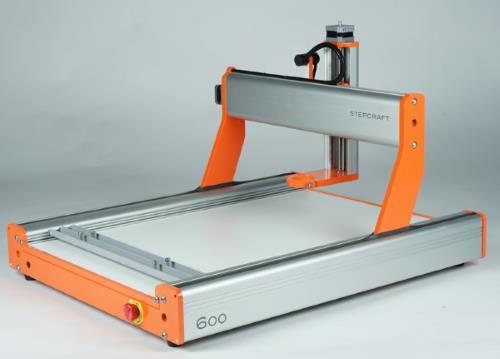
 Stepcraft CNCs are very versatile tools that have a lot of additional toolheads to be able to do a lot of different things. The only thing missing is the laser! While we understand they are developing one themselves, we will show you here how to upgrade you machine using our lasers and electronics. It is pretty straight forward, so let’s get started!
Mechanical
We have made a spindle mount laser holder for the 43mm spindle bracket on the StepCraft machine. You can purchase it in our shop or you can print it out on your own. To purchase it in the store, click here:
PURCHASE STEPCRAFT LASER MOUNT

To download and print your own mount, click here:
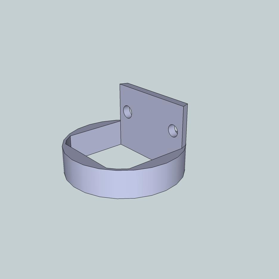
The mount for the laser will fit into the small holder on the Z axis.
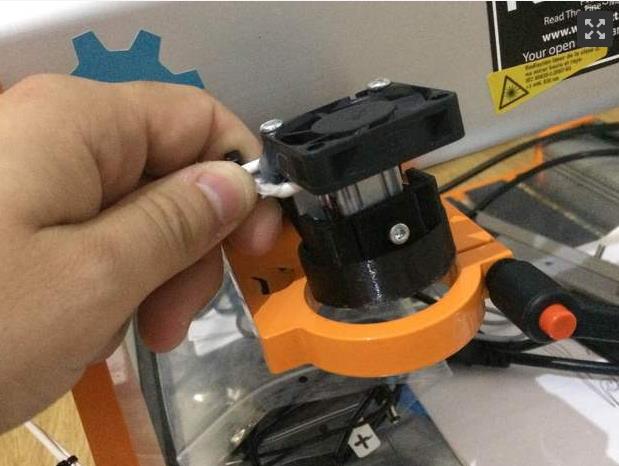
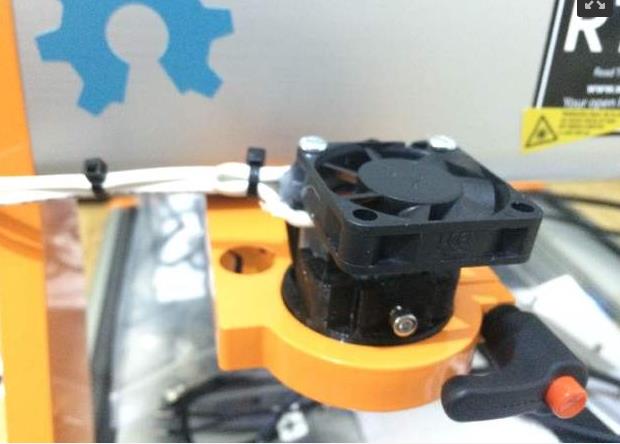
This will allow you to easily put the laser in and out and change your tool when you want to. Alternatively, you can make a mount using your CNC machine. Just design it and build it to suit. All of the dimension files for the laser and also solid model files are located here:
Electrical
There are two ways to connect your laser to the stepcraft machine:
- ON / OFF control – This will be using the spindle relay to turn on and off the laser. It is the easiest way to get started.
- PWM control – This will be using a different pin to produce a PWM signal for power control.
ON / OFF Control Setup:
Now that you have it all mechanically mounted, let’s look how to set it up to fire using your stepcraft controller. On the machine there is a DB 15 connector. On this connector there is a relay that you can control via software. The 15 pin connector is the one on the right.

From the instruction manual:
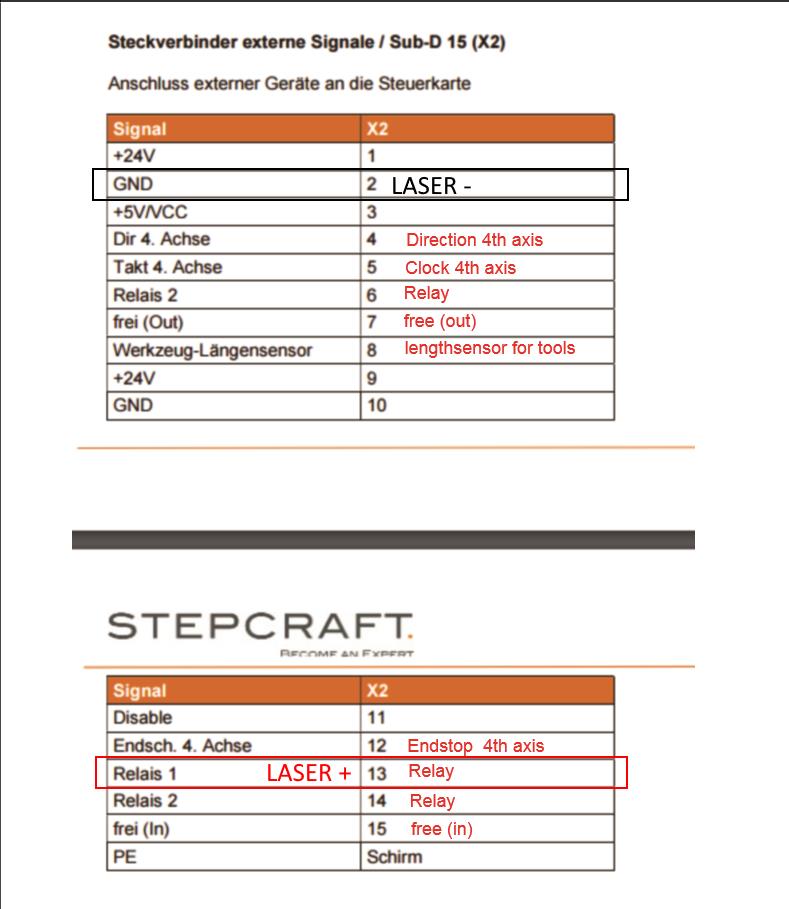
To connect the laser you will need to use the following on the DB15 connector:
- PIN 13 = LASER + (H2 + on Driver)
- PIN 2 = LASER – (H2 – on Driver)
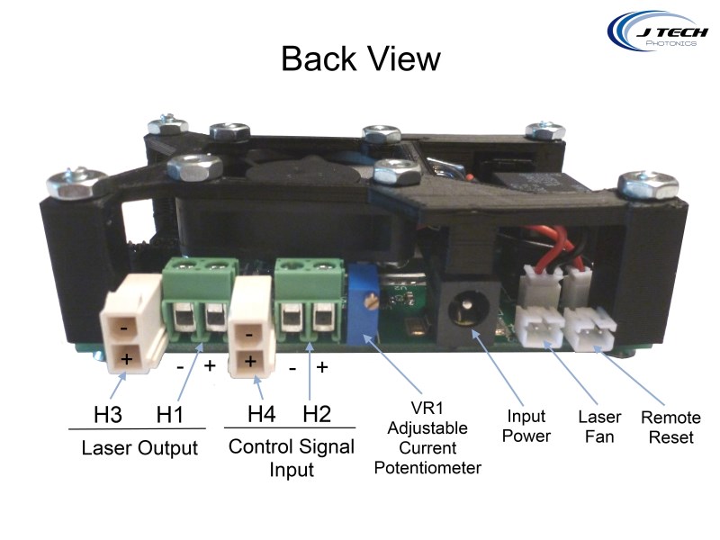
If you bought the Molex Mini Fit JR. cable then connect to H4. Make sure the positive is on the bottom and negative is on the top. If you just have the bare wires, then connect to terminal H2.
You can make your own D Sub cable if you know how to solder. You can pick them up at your local electronics shop. Or you can buy a breakout board from various locations online. Here is an example of a soldered cable.

PWM Power Control Setup
If you want to have power control, then instead of using pin 13 in the previous section for the laser “+” signal, use pin “7” instead.
To connect the laser you will need to use the following on the DB15 connector:
- PIN 7 = LASER + (H2 + on Driver)
- PIN 2 = LASER – (H2 – on Driver)
We will show how to set this up in the next section.
Software
Mach3 Setup
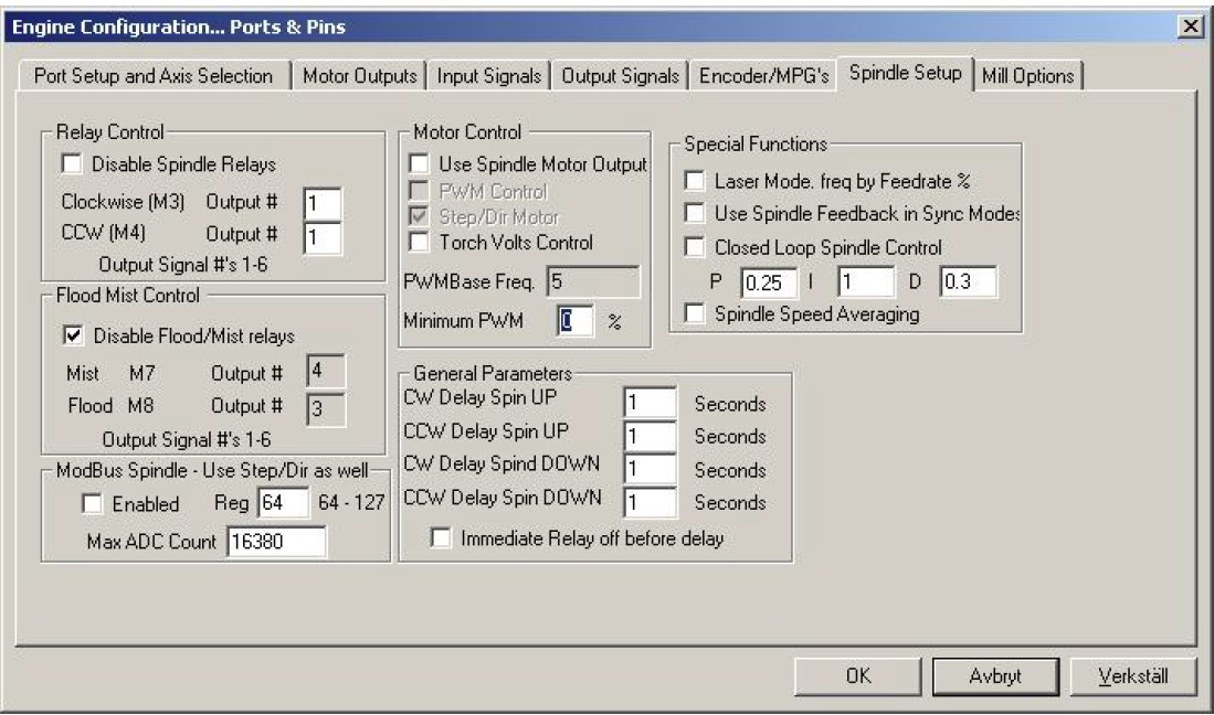
Now that you have it all hooked up, you will need to get it configured in Mach3 or WinPC-NC. Basically, you will need to set up the RELAY control from pin 13 and map it to an output. In mach 3, it is easy to map it to output #1. Once you do this, you can set it up in the Spindle setup tab. Make sure the Relay Control “disable spindle relays” box is unchecked. M3 map to output #1.
If you want to use PWM control, follow the instructions on the mach 3 page under the section “using spindle PWM to control the laser”.
Then, to turn on the laser you will use:
Laser ON command: M3
Laser OFF command: M5
UCCNC Setup
Many people are using the UC100 and the UCCNC software to run their machine. Here is the quick guide to setting up the machine.
You will need to go into the “configuration” -> “axis setup” -> “spindle” tab. This is the screen that you will use to set the laser up as a “spindle”.

In the “Configuration -> I/O Setup” page, make sure to set the “Laser Pin” like below:

In the previous section, you either set your laser driver to be connected to Pin 13 (Relay) or Pin 7 (PWM). When setting up the UCCNC controller there will be a “mapping” between the pins in the software and the pins in real life on the DB15 connector.
UCCNC PIN 1 = STEPCRAFT DB15 PIN 13
UCCNC PIN 17 = STEPCRAFT DB15 PIN 7
For ON/OFF relay control:
- Uncheck the box on “PWM spindle” and check the “Spindle relay output enabled”.
- Set M3 relay pin to “1” and port to “1”. This will map to the stepcraft Pin 13 that you have connected to the laser driver.
You can now turn on and off your laser with the “M3” command. Test it on the run screen by pushing the clockwise spindle button.
For PWM control:
- Check both the boxes for “PWM Spindle” and “Spindle relay output enabled”.
- Set M3 relay pin to “1” and port to “1” in the spindle relay section.
- Set PWM pin to 17.
- Set your Frequency to a number you want. 100 or 500 is pretty good. Anything under 5000 will work.
- Set minimum duty % to 0.
- Set maximum duty % to 100.
Now you will have control over the power using the command:
M3 SXXX
where the “XXX” is a number between 0 and 100.
Running your Laser Stepcraft
Engraving Picture
Ok, so this is probably the coolest thing you can do with your stepcraft laser – engrave images! Jim Arft, a customer of ours found this new awesome feature. We will walk through how to set up your machine here.
You are going to have to set up a “plugin” to be able to engrave pictures. You can find it on the “Configuration – > General Settings ->” tab. On the bottom left click on “configure plugins”.

A page will pop up. Click on the one labeled “Laserengrave”. Click on “Enabled” to enable the plugin.

You can click on the show button to show the plugin. You can then load an image into the plugin that you want to engrave. You have three options:
- Greyscale – This will make a 256 level image of the photo with the laser by varying the intensity.
- Halftone – This will make a “dithered” engraving of the photo with the use of dots.
- Black and white – This is used for making just black and white engravings. This is best for logos and images that have no greyscale levels.
After you have all of the settings on the right figured out as well (Feedrate, etc…) then press the “create code and send to UCCNC”. This will start the progress on the engraving.
Vector Engraving
You can generate your G Code the same as you would for your spindle, but you now are using it in 2D and not carving in 3D. You can use our Inkscape Plugin or you can generate for your favorite CAM software.
Here is a link to the software tutorials on how to do engraving:
Just make sure you wear your safety goggles when running your machine and that everyone in the area has laser protection gear. For additional safety gear you can check out the shop here: SAFETY GEAR
Here is a video of one of our lasers on a Stepcraft. Not the best quality video, but it shows it can be done.
So there it is! Now you are ready to start creating!
Buy your laser upgrade kit now!

Remember Safety First!

We sell laser shielding to block laser radiation and reflections!
Laser Goggles are also a must!
Disclaimer
The laser used in this project is very powerful and all safety precautions must be taken. Use proper safety eyewear to prevent injury to eyes. This is a project and J Tech Photonics, Inc. is not responsible or liable for any and all damage or injury caused to people or property. The use of these instructions to make a laser cutter is under your own discretion and all safety precautions should be followed. J Tech Photonics, Inc. is not affiliated in any way with Stepcraft CNC and they may change hardware and software at any time making these instructions invalid.
Thi machine how mach ?
I use a Stepcraft 600 Mk2 and am looking for a laser attachment that I can fit here in Australia and be controlled by UCCNC software.
It would have to cut 2mm ply (at least).
I have tried using yr site but most links time out and are unusable.
Can you send me manuals and prices for landed in Australia (air mail) – ideally I would not want to play around too much but just get on a use it!!
Regards
Tony Halley
Do you sell a 7 to 12 watt laser for a Stepcraft 840. We cut out parts in pine and NBF 8mm to 12mm thick.
Looking for a faster and cleaner way than a router that is slow cuts 5 to 11 times and costly on router bits and each peace has to be cleaned up after.
We have been told that 3.8 may not be powerful to cut 12mm pine is this true?
Please can you send prices and delivery to Australia for the Stepcraft 840
Kind Regards
David Richardson
Hello,
I’m using UCCNC and a breakout board to drive my J Tech laser. I have the B port available on the board and would like advice regarding how to connect the laser input from the breakout board for PWM control. The pins available are
Pin 1 – X/Y/Z/A/B Enable
Pin 4 – B – Step Pulse
Pin 17 B – Direction
GND
I’m using shielded cable. Should I put the shield braid into the GND connector?
is it not possible to use the PWM adapter for the spindle as a PWM adapter for the laser?