

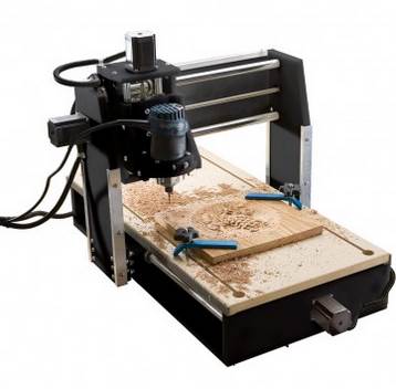
We have gotten a lot of requests for upgrading the CNC shark by Next Wave. It is a nice woodworking tool that can do a lot of projects in your woodworking shop. Now how about adding a laser? Of course you can! It is not very hard if you have the newest version of the control box. We now have a Laser kit that is fully integrated with the Shark controller that allows it to seamlessly work with Vectric and Next Wave Automation software.
Laser Upgrade for HD4 and HD5 machines
We are going to go over how to install the J Tech laser on the Shark HD4 and HD5 machines with the newest controller box.
Laser and Fan Extension Cable Installation
Insert the laser spindle shaft into a 1/4″ collet on the spindle or router and tighten snuggly.
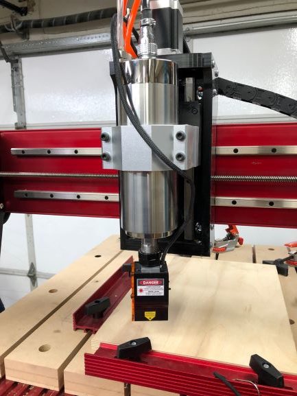
Run the cord around from behind the spindle/router ensuring that it is clear of any Z axis movement. A Velcro strap was used here to hold it in place. Anything can be used to temporarily hold the cord if it will stay secured.

Continue running the cord up the spindle/ router to join with the power cord and cooling water lines if present.
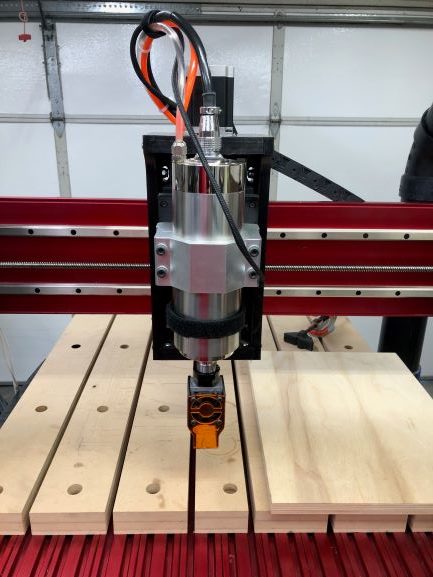
Keep running the cord over the top and temporarily secure to the other lines.
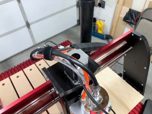
Complete running the cord by bringing up to the beginning of the chain
Open the cable chain behind the gantry and insert the laser and fan power cords.
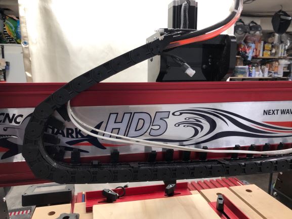
After running the cords in the cablechain close all the clips.

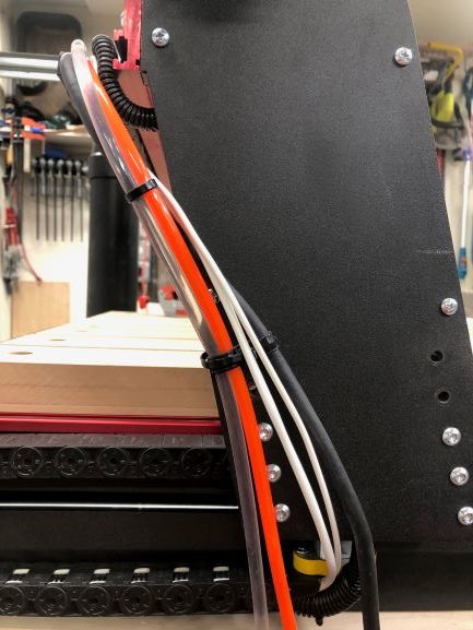
Now connect the extension cables to the laser and fan cables.

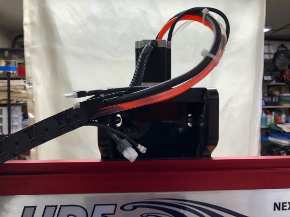
Continue running the cables down the gantry leg to the front of the base cable chain.
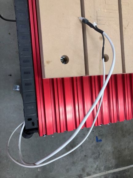
As with the cable chain on the gantry, open the clips and lay the cords inside being sure to avoid any kinking or pinching of the cords. Afterwards be sure to close all the clips.
This will leave just over 18” at the end of the cable chain at the front of the base using a 10’ cable extension. Cable lengths of up to 25’ are available.
Laser and Driver Installation
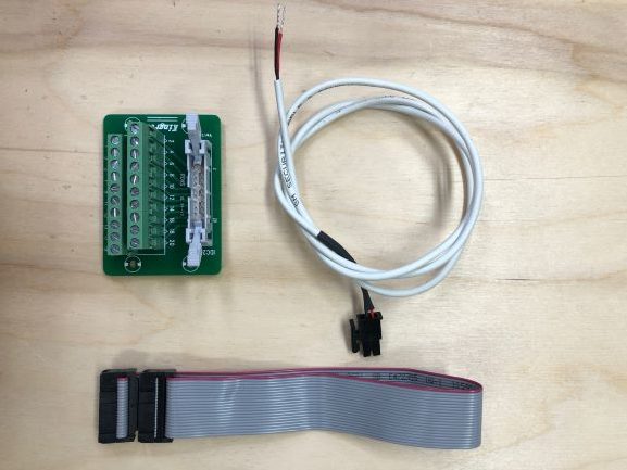
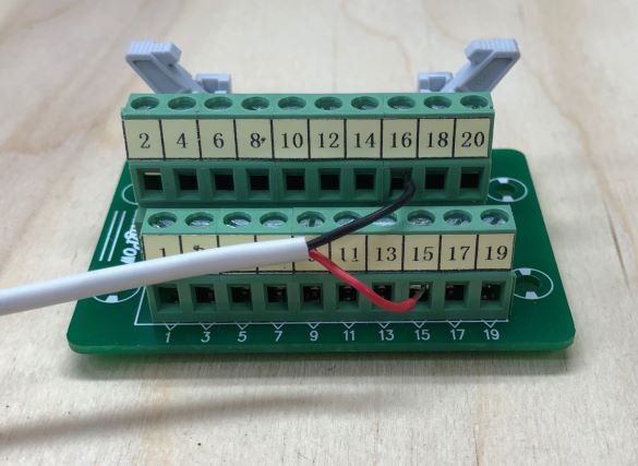
The Shark HD interface kit includes a breakout board, ribbon cable, and input cable for the laser driver. They are shown here:
Using a small flat screwdriver loosen the screws on binding lugs #15 and #16. On the breakout board. Connect the control signal cable to the breakout board as follows;
Insert the RED wire into #15
Insert the BLACK wire into #16
Tighten the screws snuggly.
Both ends of the 20-conductor ribbon cable are identical and can be used end for end, but they are keyed and can only be inserted one way.

Plug the ribbon cable into the breakout board by opening the locking arms and lining up the key on the cable and the slot on the board as denoted by the red arrows in the picture.
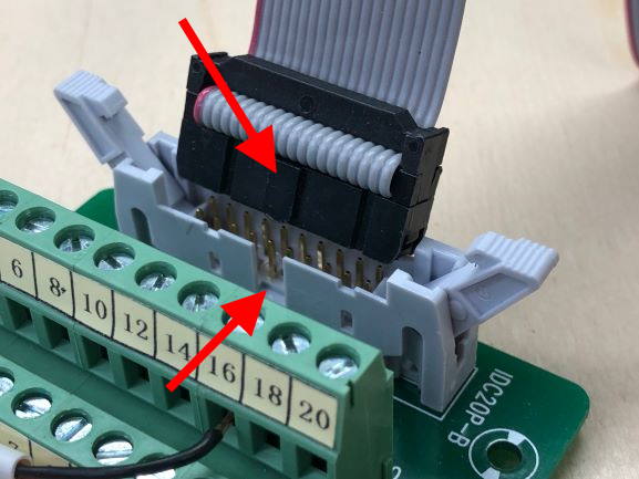
Press down evenly and firmly while inserting the cable. As the cable is inserted the locking arms will close onto the connector locking it in place.
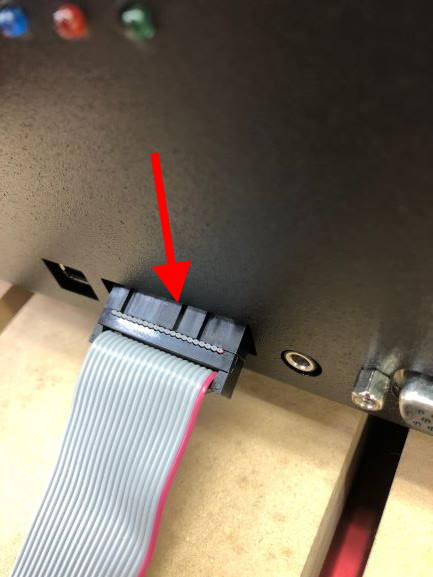
Locate the 20-conductor connector on the front of the CNC controller. You will see the slot is on the top of the connector as denoted by the red arrow.
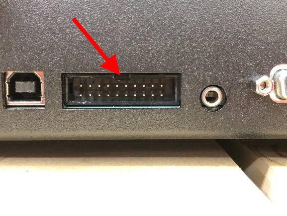
Position the breakout board on top of the controller. This will help line up the cable as it meant wrap back onto itself so the board and laser drive can mount on top of the controller.
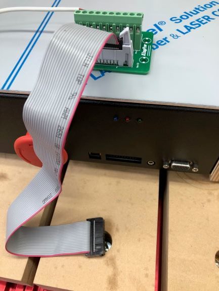
Insert the ribbon cable into the controller with the key facing up as shown in the picture making sure it is firmly seated all the way in.
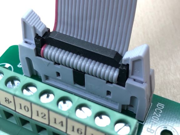
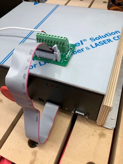
It should look like this when completed.
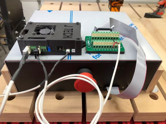
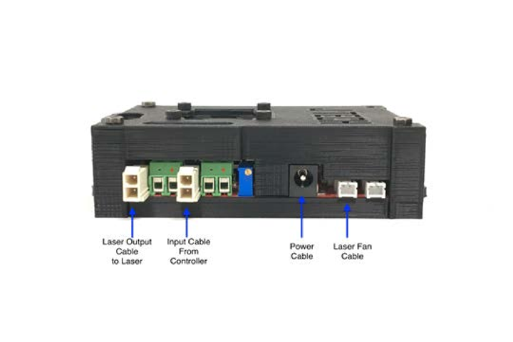
Connect all of the cables to the back of the laser driver to complete the installation.
Software
We recommend using the vectric laser module for your CAD software. Use the Shark post processor included in the laser module when doing your laser files. Output the toolpath file like you normally do for carving and run it on your shark controller. Note, it will not do photo engraving unless you use the “Ready to Raster” program from NextWave. We have not had any good results when using this, so I wouldn’t count on doing photos. You could alternatively use the “laser end mill” post processor found here.
If you don’t have the Shark laser post processor, then you can find it here as well.
Older Versions using the Spindle Relay
Electronics
There are several versions of the CNC shark that have been developed over the years. You need to look at your controller and see if it has an output for the spindle to turn it on and off. Many of the newer models like the MAKO have this feature. If you do, then you are in luck! The spinde control uses a relay to switch the power on and off to the spindle. This relay is controlled by a DC voltage signal. This is the signal we need to turn on and off the laser.
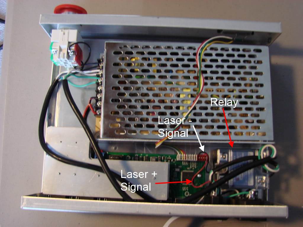
If you open up your controller box, it should look something like this:
You are going to use the signal from the control board to the spindle relay and connect it over to the laser driver board input. Here is a more detailed picture:
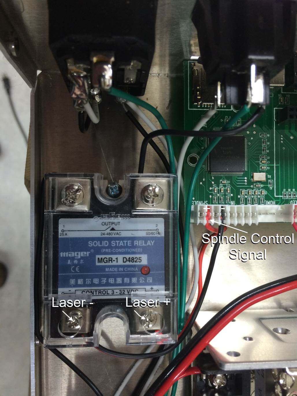
Attach a wire from the relay “+” signal to the laser driver “+” terminal H2. Attach another wire on the relay “-” signal to the laser driver “-” terminal H2. Or, you can use the 3′ Molex Mini fit cable and connect it into terminal H4 on the laser driver:

That is it, you are done!
Controlling the laser
You now can control your laser on and off using the same spindle commands of M3 to turn on the laser and M5 to turn it off.
Remember Safety First!

We sell laser shielding to block laser radiation and reflections!
Laser Goggles are also a must!
Disclaimer
The laser used in this project is very powerful and all safety precautions must be taken. Use proper safety eyewear to prevent injury to eyes. This is a project and J Tech Photonics, Inc. is not responsible or liable for any and all damage or injury caused to people or property. The use of these instructions to make a laser cutter is under your own discretion and all safety precautions should be followed. J Tech Photonics, Inc. is not affiliated in any way with Next Wave and they may change hardware and software at any time making these instructions invalid.
How do generate a file to download to the shark that will turn on/off the laser correctly to engrave a design? The typically router software just turns on the router at the start on the operation and off at the end.
You can use our G Code generator plugin for Inkscape that you can download from here: https://jtechphotonics.com/?page_id=1980
You use M03 to turn the laser on and M05 to turn it off. This has been verified to work with the control software you normally use with your router. You can use many other programs to generate the G Code as well including our raster sw “laser etch” here: https://jtechphotonics.com/?product=laser-etch-bw-image-engraving-sw-license
If I’m understanding correctly, the Inkscape or Laser Etch solutions will allow you to use a Shark to cut designs by controlling the on/off function of the laser, correct? It’s not capable of doing laser engravings that are dependent on controlling the power of the laser as it moves using PCM for input or some kind of converter? Still trying to figure this out. The on/off capability is a great starting point for me, just wondering if there is a ready made PWM or other type of controller package for a Shark type CNC machine that doesn’t have to be built from scratch? A lot of information here, thanks!
Hi Dave,
You are correct. As it is right now the Shark upgrade instructions only support the “ON/OFF” of the laser. You can use the inkscape and the laser etch software, but can’t use the PWM function of the PicLaser software. You can do “dithered” images however. These are the ones with all the little dots.
Has anyone figured out which pin on the front of the CNC Shark HD4/5 controls laser power?
how can i talk to a real breathing person, I’m new to this but very interested in a laser but have no idea what i need. home phone
850 587 1212
Not sure if this thread is still active. I am hooking up an Atomstack 50M to my shark HD4. If I understand this the Spindle output is being used as the TTL for the laser control. Is this Correct? Is that output 5vdc.
Thanks