

![]()
Laser Upgrade Implementation
So I just bought a Solidoodle printer and now I want more! Let’s make it a laser cutter as well! Here is how to implement the J Tech Photonics laser upgrade kit to the Solidoodle printers.
First things first, you need to figure out what you have on your particular machine. Solidoodles have been shipping for awhile, and they are always changing and improving them. So, take a look and follow the instructions for whatever hardware you have.
Solidoodle 4, Workbench, & WB Apprentice:
Upgrading the new solidoodle machines is super easy! We are going to take the fan that is connected to the board and replace it with the laser connection. The fan is located here:
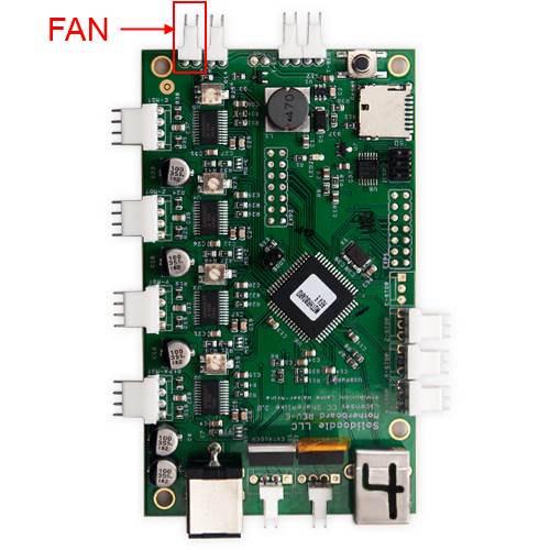
When you want to use the laser, replace the connector for the fan for another molex style connector that attaches to the laser driver board control input screw terminal H2. Then use the M106 Sxxx command for “laser on” and M107 command for “laser off”.
You can get the connector here at the shop. You might consider putting in a SPDT switch instead of swapping the cables. Just cut the fan positive wire and put the part coming from the PrintRBoard in the center, the one going to the fan on one side and a new wire going to the laser driver on the other. Just also connect the ground to the laser driver and you are set! Then you can have a nifty switch to go between 3D printing and laser cutting!
Of course, you will need to print out a mechanical mount for the laser as well. The dimensions and solid models are located in the documents section of the website.
Software for using your new laser upgrade is located here in the software section:
Click here for free Software for your laser upgrade
Solidoodle 1,2, & 3:
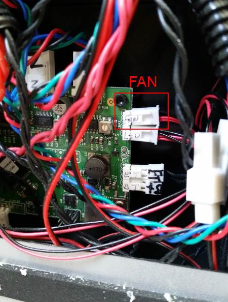
1. I have a PrintRBoard with a fan connected to the fan output:
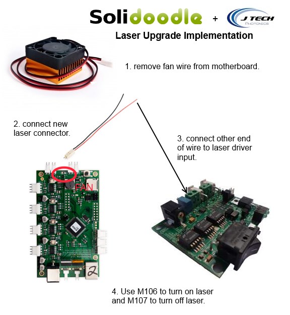
It is pretty straight forward. The Solidoodle printers use a version of the PrintRboard from the RepRap project. It has an output for a fan, which Solidoodle uses on top of their extruder. When you want to use the laser, replace the connector for the fan for another molex style connector that attaches to the laser driver board control input. Then use the M106 command for “laser on” and M107 command for “laser off”.
You can get the connector here at the shop. You might consider putting in a SPDT switch instead of swapping the cables. Just cut the fan positive wire and put the part coming from the PrintRBoard in the center, the one going to the fan on one side and a new wire going to the laser driver on the other. Just also connect the ground to the laser driver and you are set! Then you can have a nifty switch to go between 3D printing and laser cutting!
Of course, you will need to print out a mechanical mount for the laser as well. The dimensions and solid models are located in the documents section of the website. If you remove your extruder and only use it as a laser, then the mounting holes for the extruder are matched exactly to the mounting holes on the diode. You will need to add about 1″ of some material to the right side of the laser so the head will trip the limit switch correctly.
Here is the graphical version of the instructions:
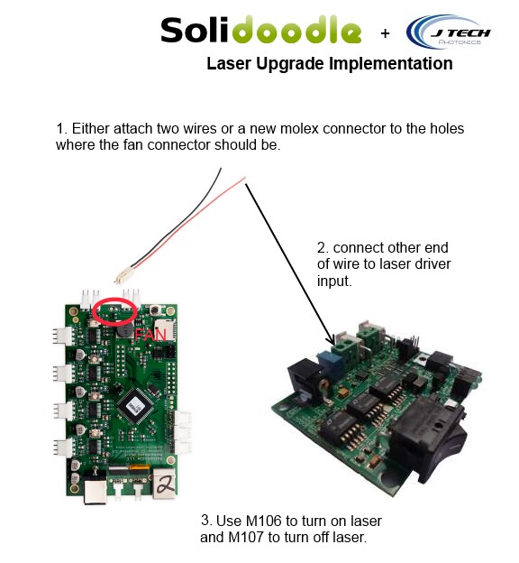
2. I have a PrintRBoard with nothing connected to the fan output:
Again, pretty easy. With this one, simply connect two wires (one positive and one ground) from the output of where the fan connector should be to the input of the laser driver. Or alternatively, get a new molex connector with wires here at the shop and solder it to the board. Connect up positive to positive and negative to negative and you are set! Then use the M106 command for “laser on” and M107 command for “laser off”.
You can do the same thing with the switch and the mounting as in the instructions for #1. Here is the graphic for this one:
3. I have totally different board than the PrintRBoard, help!
If you look at your machine and it does not have a PrintRBoard, then you probably have one shipped with a sanguinololu board. It still can be upgraded, but is a bit more of an effort. Your board probably looks like this:
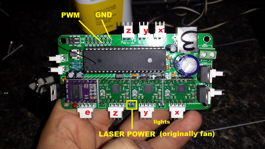
The board has some extra stuff in it like analog outputs and PWM. The IO header has a PWM output as well as 5 analog outputs you can use. A Solidoodle 2 owner, Ian Johnson, has made a pretty good write-up on how to add a controllable fan to the sanguinololu board here: http://solidoodletips.wordpress.com/2012/10/26/gcode-controlled-extruder-fan/
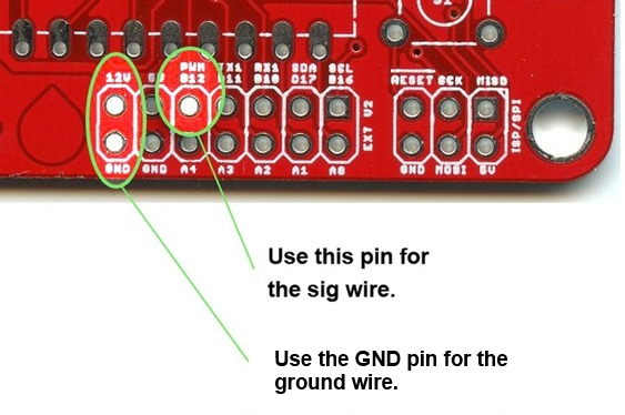
You won’t need to bother with the mosfet driver, because the input for the laser driver is a digital isolator that only needs a couple of miliamps to turn on. So, all you need to do is connect up the IO header to the input for the laser driver. If you bought the OEM kit from us in the shop, then you can use the header in the picture about that says “LASER POWER” to power the laser driver board.
The cool part is that you are using the PWM output from the board. This means you have power control! Adjust the laser driver potentiometer to have the maximum power level you want, say 1amp. Then, use the speed command as part of your G Code. The laser power can then be adjusted on the fly from 0 to 255 levels. For all on, use M106 s255. To turn it on half power it is M106 s127. To turn off the laser, use M107. Just modify your G Code file for your part to put in the levels you want. Repetier host also has a button and a slider to control the laser (it will be marked “fan”).
Ian mentions that you might need to modify the firmware as well. He writes from his post:
“The fan may not already be activated in firmware, so follow the directions here for how to download and update the firmware. When you have the firmware open in Arduino, change to the Pins.H tab. This will probably be too far down to appear at the top of the screen, but on the right side there will be an arrow that pulls down the full list. Scroll about halfway down, looking for the section for Sangiunololu. In that section look for
#define FAN_PIN -1
and change the -1 to 4.”
Here are some mechanical pictures of before and after:
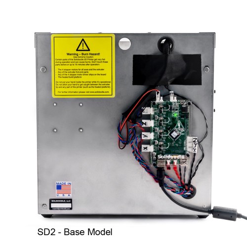 The 2nd and third generation machines all have the control board exposed, allowing for the swap of the connector to be easy.
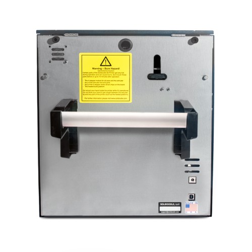
The 4th generation machine is not exposed, so it might be best to get a SPDT switch and wire it once.
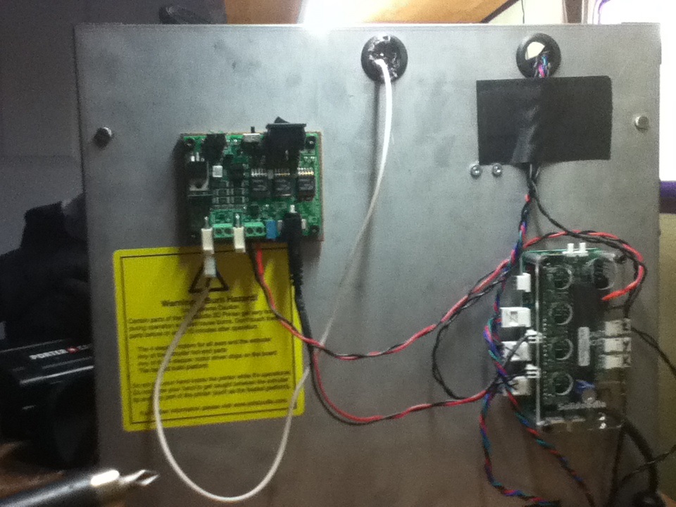
Here is an upgrade showing placement of the laser driver on the back of the machine in a solidoodle 3.
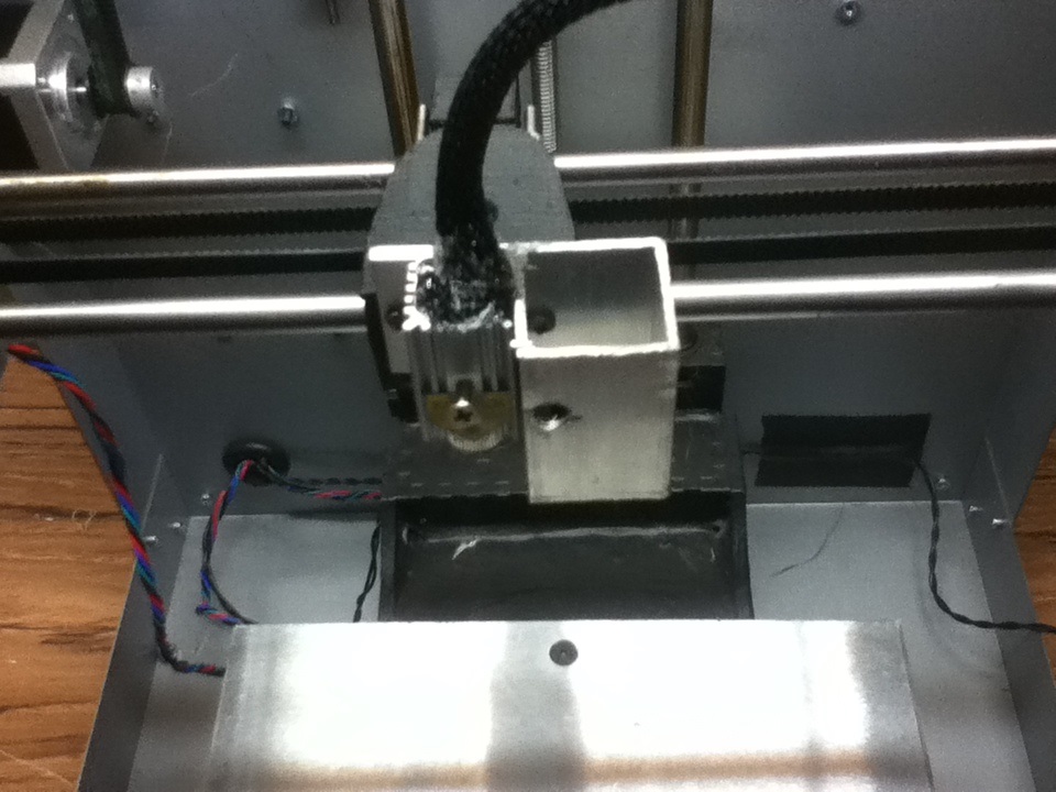
If you remove the extruder head, the laser diode mounts directly to the plate. You need to add about 1″ of something (you can print out a block) to put beside the laser so it hits the limit switch correctly.
Buy your laser upgrade kit now!

Remember Safety First!

We sell laser shielding to block laser radiation and reflections!
Laser Goggles are also a must!
Disclaimer
The laser used in this project is very powerful and all safety precautions must be taken. Use proper safety eyewear to prevent injury to eyes. This is a project and J Tech Photonics, Inc. is not responsible or liable for any and all damage or injury caused to people or property. The use of these instructions to make a laser cutter is under your own discretion and all safety precautions should be followed. J Tech Photonics, Inc. is not partnered in any way with Solidoodle and they may change hardware and software at any time making these instructions invalid.