


Who doesn’t want a laser for a Shapeoko3 CNC? We have had great success with the original Shapeoko 1 and 2 upgrades, so it is not much different. We have had the opportunity to upgrade a Shapeoko 3 in the lab and it runs GREAT! It is a really stiff machine and the components are all built well and in the USA! Good job to the guys over at Carbide 3D on putting out another great Shapeoko kit. Now lets get started!
We will walk you through the electronics hook up, the mechanical assembly, and the G Code needed to run. It should take only a few hours total from unboxing to running.
Mechanical
We have made a custom 3D printed mount for the Shapeoko 3 so the laser can fit right next to the Spindle without needing to take the laser off whenever you want to carve. The mounting kit is located in the shop and contains everything you will need to get your laser on the Shapeoko 3 and running. This is in ADDITION to the laser kit you ordered and is specific for the Shapeoko 3 CNC. It includes:
- Power Extension Cord: For extending the power to mount the driver on the electronics box.
- Laser Mount: To put next to the spindle holder for the laser.
- Laser Mount Screws/Nuts: To mount the laser on the laser mount.
- Laser Driver Mount Screws/Nuts: Screws to attach the driver to the electronics enclosure.
- Zip Ties: To clean everything up for cabling.
- Zip Tie Holder: To place on the Z axis gantry to hold the laser cable in place and out of the way.
- Press Fit Connector to put in the carbide board for the PWM signal.
- Press Fit Tool used to push in the press fit connector.
- Molex Mini Fit Jr. input cable to attach to the Carbide Board press fit connector and the laser driver.
The Shapoko 3 XL and XXL kit includes everything above, as well as the laser extension cable and extended fan upgrade so you can mount the driver on the side of the machine where the electronics are.
Purchase Laser and Mounting Bundle Here
Electrical Hook Up
When connecting a laser for a Shapeoko3 CNC we want to make it easy. We have upgraded the mounting kits to include a “press fit” connector to push in a connector to the PWM and GND signals on the carbide board versus soldering it in. It will make the installation much easier to do. If you purchased a shapeoko3 mounting kit before 8/22/2018 without the press fit connector in it, please contact us and we will send you one for free.
Video Installation Instructions
Check out the new video instructions here
Lightburn Software Setup Video
We recommend lightburn software for running your laser. This video shows how to set it up.
Step By Step Instructions:
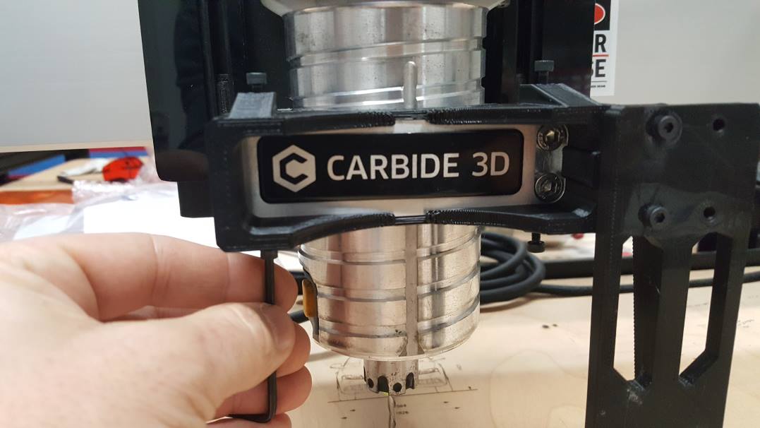
All Lasers use the new Metal Front Mount
Step 1: Remove Screws from Spindle clamp.

Step 2: Use Provided M5 screws to attach Metal Mount

Step 3: Attach Laser
Put the two screws into the top of the key holes and the magnets will pull it down


Optional: Tighten back screws to lock the laser in place for better stability
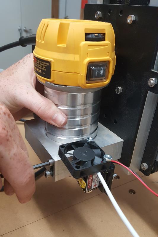
Step 4: Connect the laser to the Extension Cable

Step 5: Connect the air tubing to the air assist
5a) Remove the nut from the connector.
5b) Place air tubing through the nut.
5c) Put the tubing over the pneumatic barb
5d) Tighten the nut

For older Versions
Step 1: Assemble the laser to the Shapeoko3 laser mount.
For older laser for a Shapeoko3 CNC, there are two mounts for the shapeoko3 that come in the bundle:
- Standard Magnet Mount – Center and Right Side Options


- Dust Boot Magnet Mount – Designed for the Suckit Dust Boot

The standard mount has two locations to mount to. The dust boot mount has an opening in the front to allow for a dust shoe hose to fit.
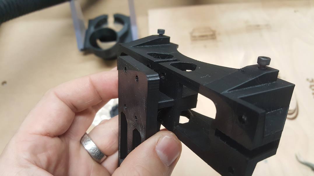
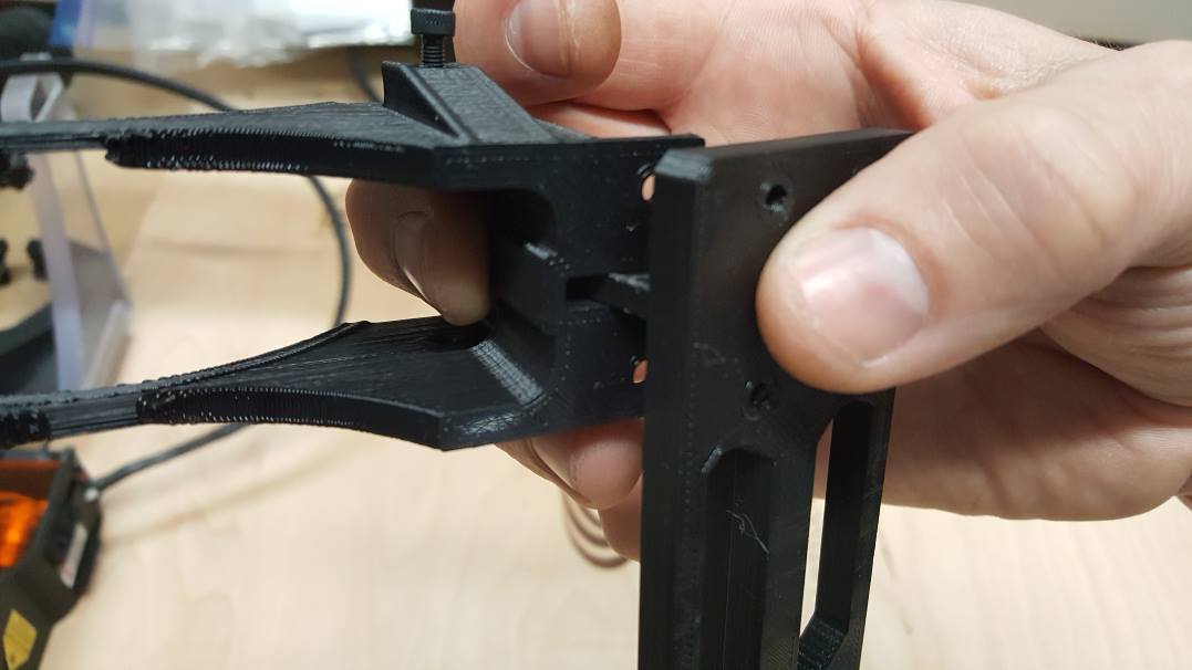
It is easiest to put the laser holder onto the base mount first. Then attach the mount to the front of the aluminum spindle holder. We will start with the Standard Mount.
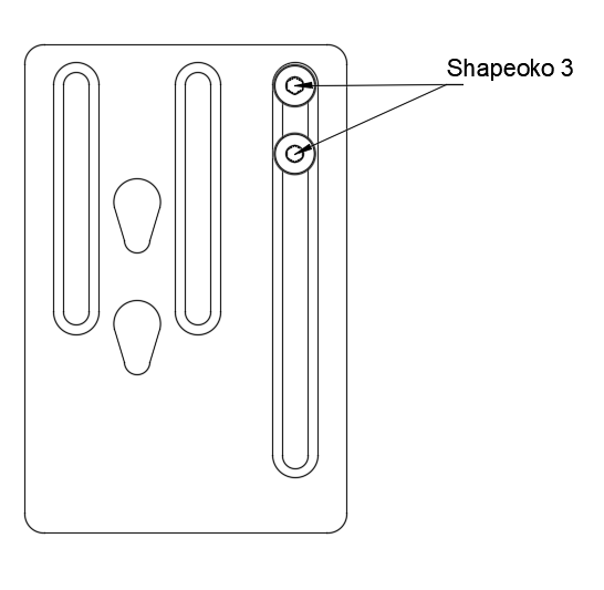
Standard Magnet Mount Installation
The laser for a Shapeoko3 CNC will have two choices on placement on this mount. Either in the front, or on the right side. In this example, we have it in the front.
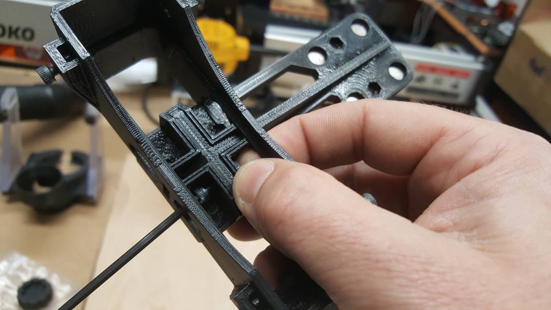
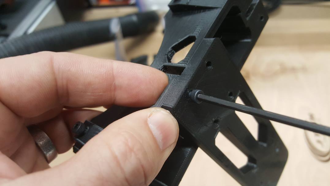
- Put the laser holder into the mount. Push it in so the holes line up. It might take some force as it is a snug fit.
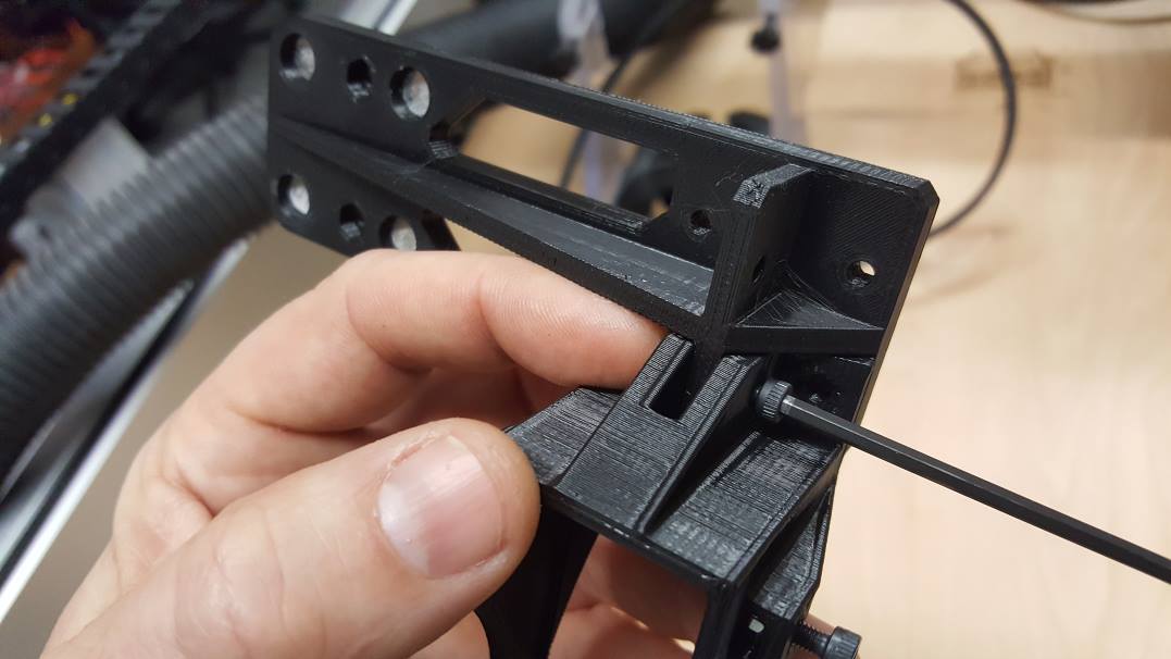
2. Put the M3 nuts in place for the screws.
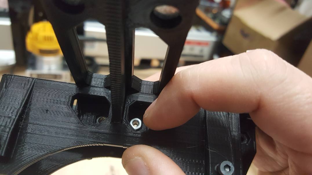
3. Hold the nuts with your finger and put the M3 12mm scres in the top.
3. Do the same for the other M3 12mm screws in the front.
4. In this example, you will use all 4 of the front locations. If you choose the side, you will only need two in the front.
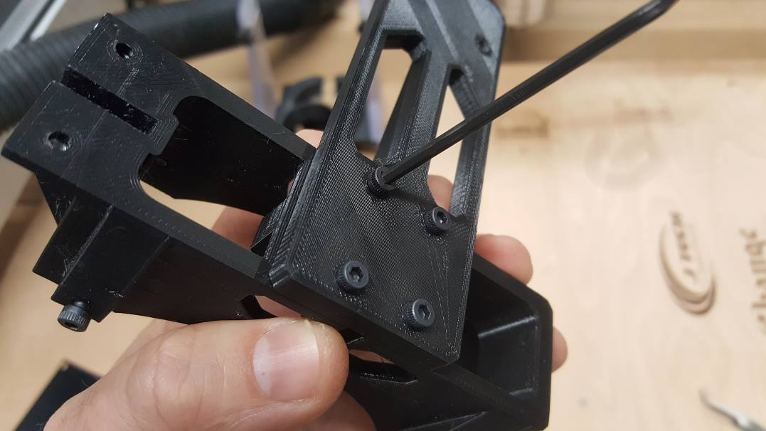
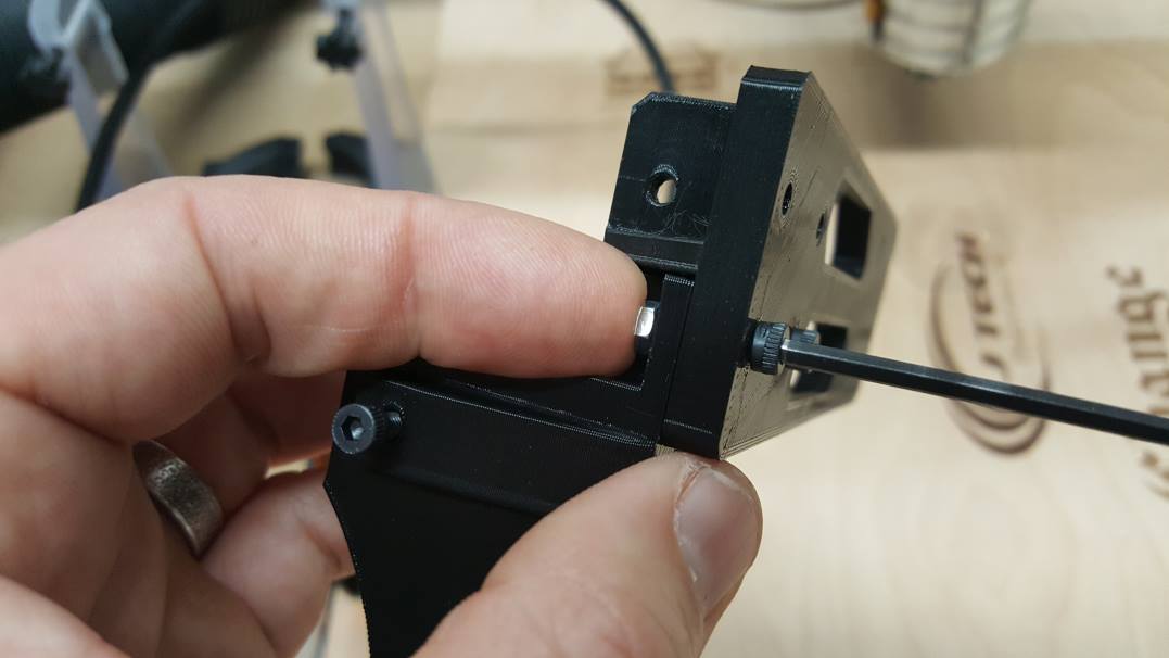
5. Place the full mount on the front of the spindle holder.
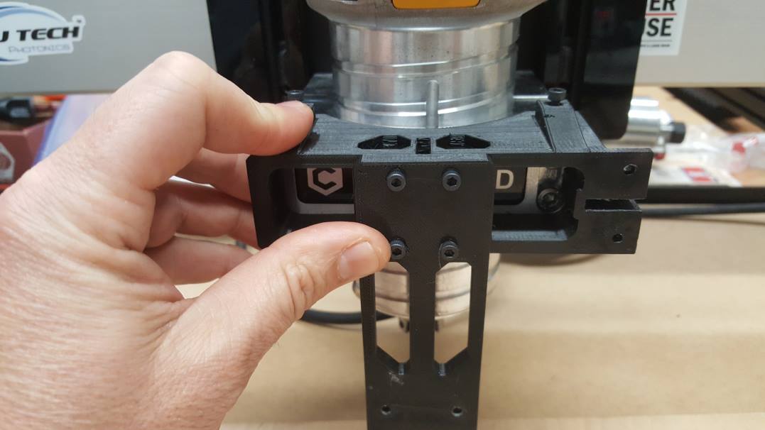
6. Screw down the bottom and the top M3 10mm screws to hold the mount to the aluminum spindle block. Do Not OVER TIGHTEN! Now you are ready for the laser.
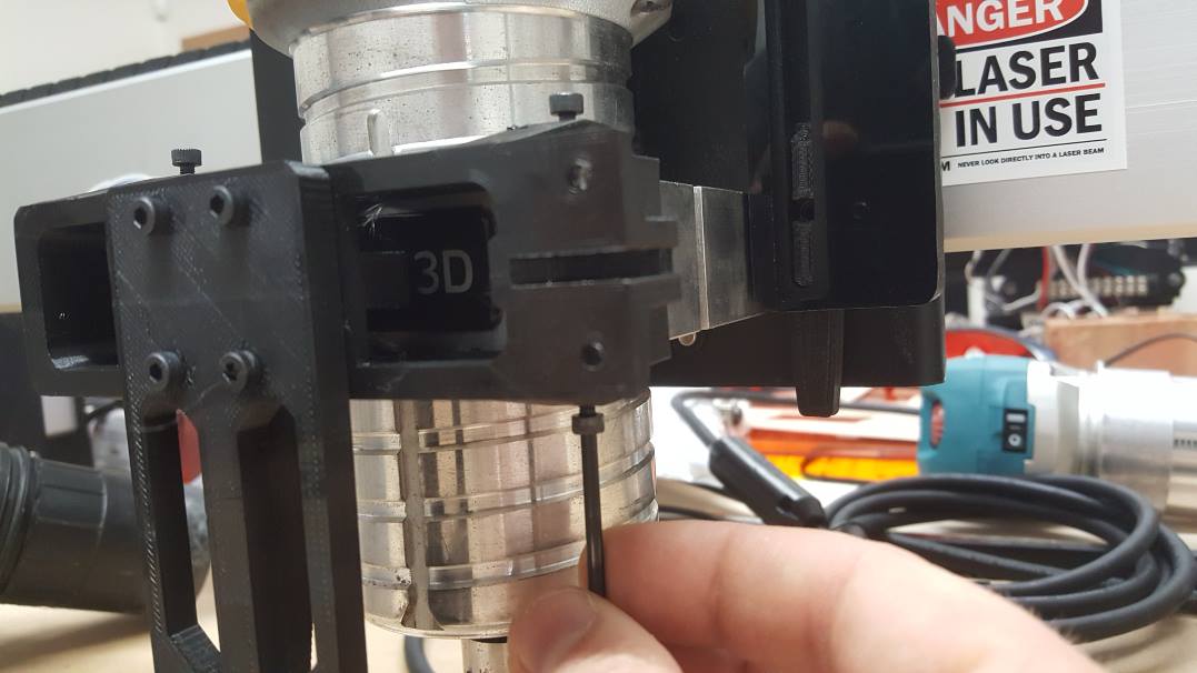
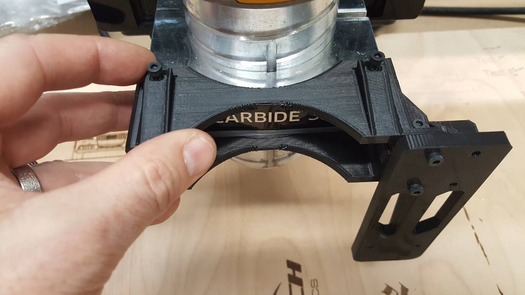
7. Push the laser onto the magnet mount.

Dust Boot Magnet Mount Installation
This mount is designed for use with the Suckit Dust Boot, but it can work with others as well.
- Put the laser holder onto the main mount on the side. Push it in so the holes line up.

2. Put the bottom M3 12mm screw in.
3. Put the front two screws in.
4. Put the Mount onto the aluminum spindle holder.
5. Screw down the bottom and the top M3 10mm screws to hold the mount to the aluminum spindle block. Do Not OVER TIGHTEN! Now you are ready for the laser.
6. Push the laser onto the magnet mount.
For Older J Tech Kits with the old style mounts:
Remove the two screws holding the spindle in the holder and place the laser mount in. Put the screws through the mount and tighten with an Allen wrench. This is showing the short 2.8W mount.
Here is an example of the magnet suckit side mount installation. All of them use the two side screws to attach. The magnet suckit side mount will also go in the front as well as the side.

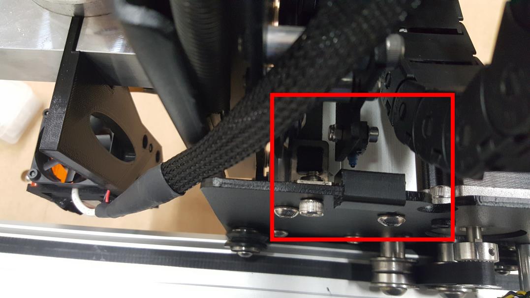
Step 3: Route the extension cables (for XL and XXL machines).
Make sure you keep the end that connects to the laser by the Z Gantry as shown in the picture. Hold it in place with a zip tie.

If you plan to put the extension cables in the cable chain, Make sure your put tape on the end you are pulling so they don’t get stuck.

We just put ours on the outside and just zip tying the cable to the outside like in the picture:

Go along the entire X axis cable chain:

Then, go along the Y axis cable chain over to the electronics box.

Bundle up the extra with some zip ties:

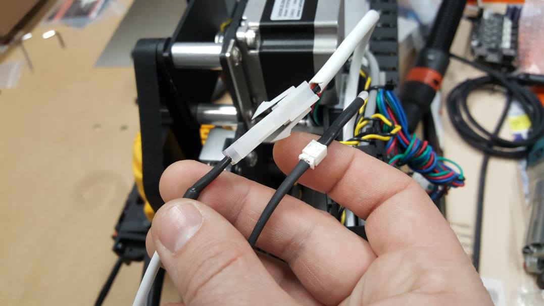
Step 4: Connect the Laser to the Extension Cables
Zip tie the end of the laser and fan cables to clean things up.

Connect the laser and fan cables to the extension cables on the top of the machine. Make sure they are not interfering with any other parts of the machine.
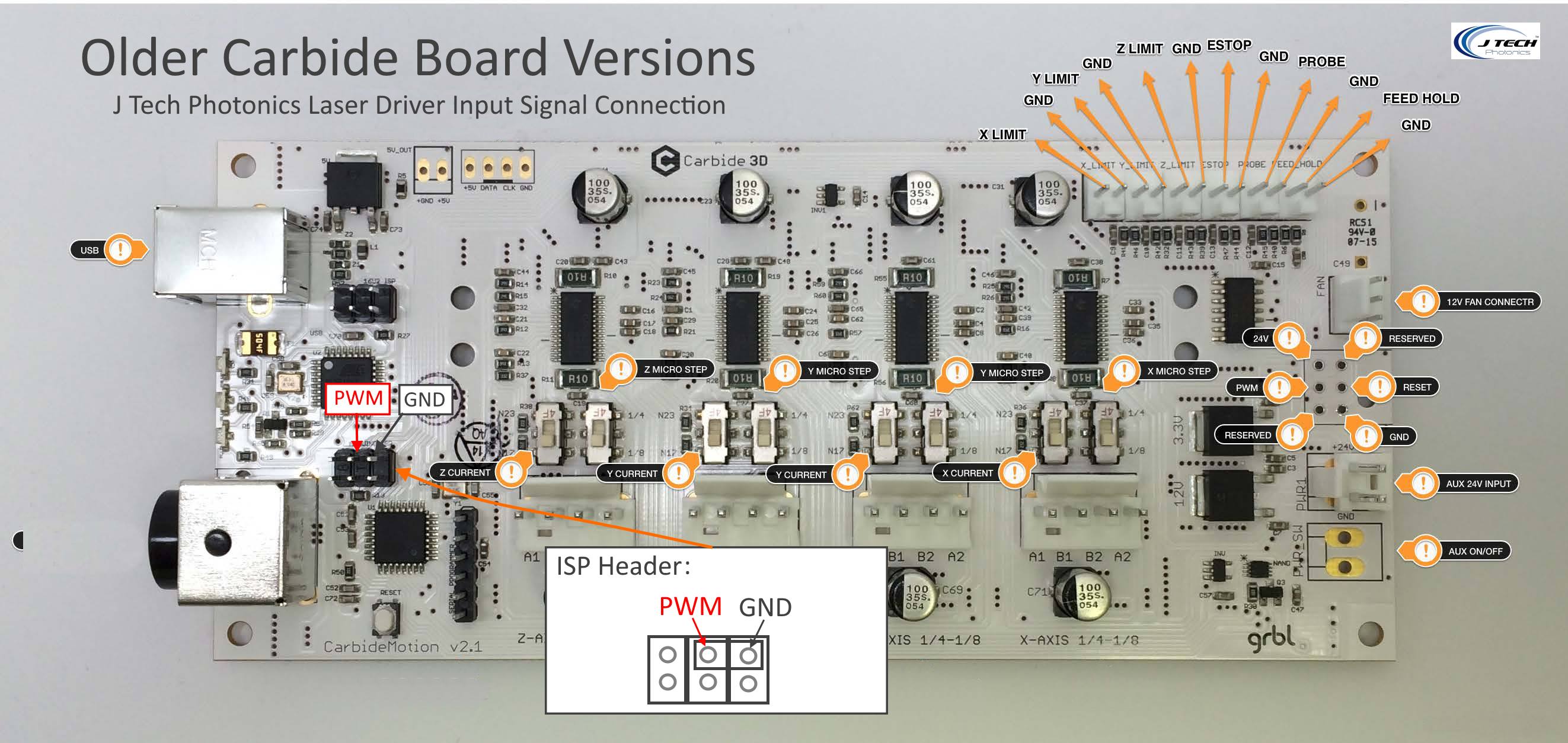
Step 5: Take off the cover on the Carbide board and Connect the PWM Cable.
Carefully take off the box covering the circuit board on the side of the machine. We will be using the press fit connector to make our connection to the carbide board to the laser driver.
The signals we need for the board are here:
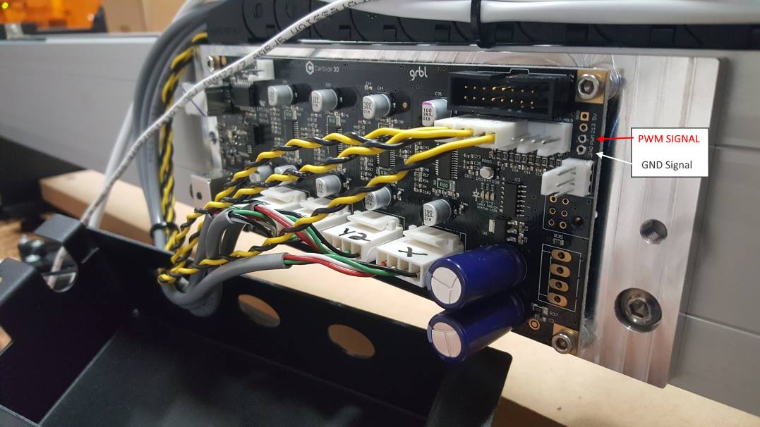
Put the two pin header into the holes marked PWM and GND.

Here is a small video showing how to press the connection in:
If you have trouble with the press fit connection or you rather connect to a different place on the board, then you can connect to the “ISP” header on your Carbide board. Here is a video showing how to do this:
Here is the back of the laser driver. Use the included cable from the mounting kit to connect to the Carbide board (RED wire to PWM and BLACK to GND). Connect the other end to the laser driver H4 signal.

If you have an older version of the Carbide Board, then connect the two pin wire to the following “ISP” header as shown in the picture below. Make sure you put the RED WIRE to the PWM post in the header. Connect the BLACK wire to the GND post in the picture.
Step 5: Mount the Driver on the back of the Electronics Enclosure
*note* You don’t have to mount the driver on the machine. You can just put it next to it on the table… We thought it would look cleaner if it is on the back of the enclosure but it is easier just to leave it on the table.
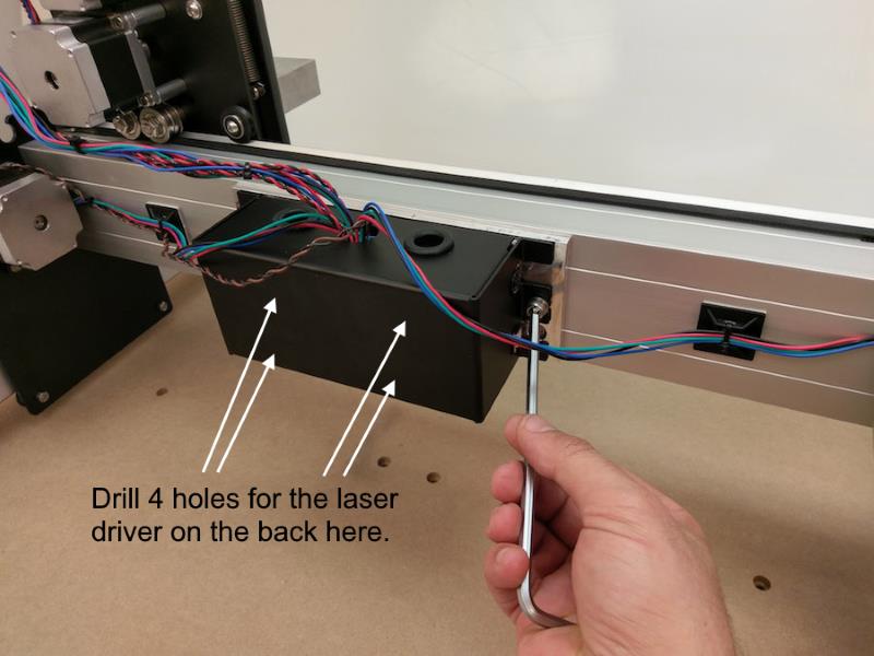
If you choose to mount the driver it depends on which version of the Shapeoko3 you have. We have an early one, so our enclosure has some holes already drilled that we decided to use. If you have the new black enclosure, then you will need to drill some holes to mount the driver.
For the new standard kit the enclosure is now black and fully enclosed. You can take the four outer screws from the driver off and then use the bottom plastic base plate that says “J Tech Photonics” on it to measure where the holes should be. Drill 4 holes that will fit #6-32 screws. Use the included 4 #6-32 1 1/2″ screws in the mounting kit and replace them in the driver to be able to mount it to the back of the enclosure. When using the new black enclosure, make sure the Fan is facing the outside so there will be airflow to the driver.
Change the screws out for the longer 2″ screws to go through the black enclosure.

Put the screws back in the opposite direction so the J Tech Photonics side is on the bottom and then you can slide the screws into the enclosure holes and use the nuts to tighten it all down.
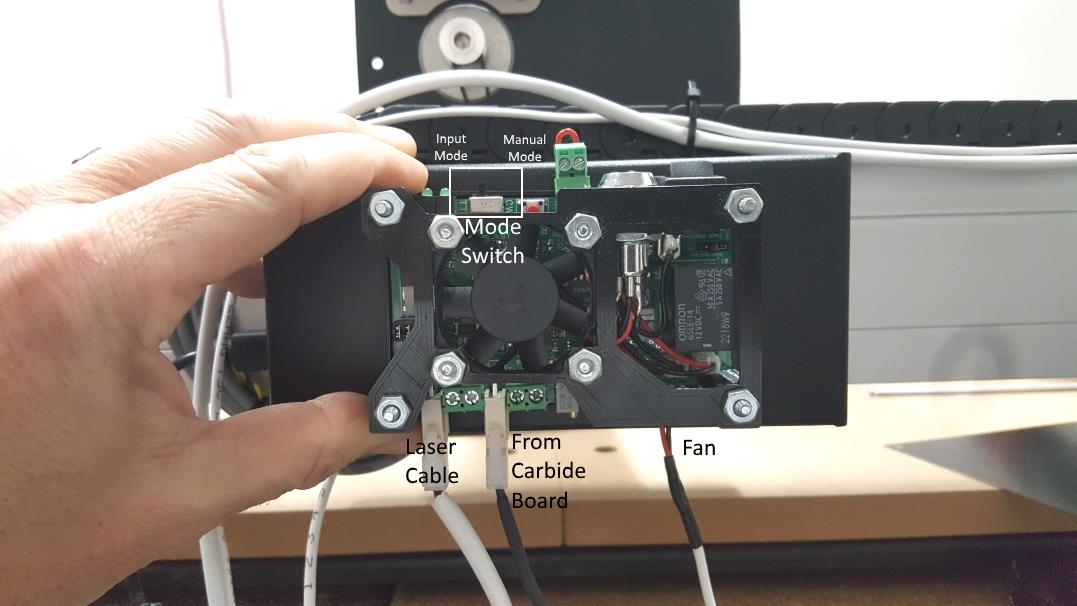
Step 6: Plug in the cables to the laser driver
You are going to now connect the cables to the mounted driver. Make sure to put the laser and the control cables in the correct positions.
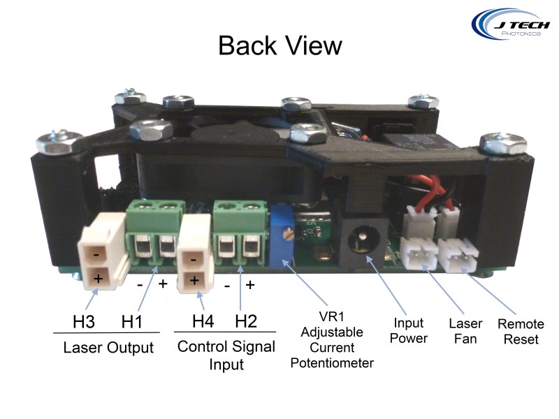
Connect all the cables to the driver. If you mounted yours to the black enclosure then you will have the “J Tech Photonics” side facing the other way.
*note* we don’t show the power cable connected. It goes between the fan and the input control cable. You can just run it next to the power cable for the shapeoko 3.
Step 7: Limit Switch
*****UPDATE 2-20-2019******
This limit switch block is only for older style mounts. The newest magnetic mounts do not need the limit switch block.
******************************
For the larger magnet versions of the mount, they will be slightly too large for the limit switch on the X axis to hit. You can put a small object attached to the X axis for the switch to hit it when homing. There is an included “limit switch block” in the shapeoko3 mounting kit for this purpose. You can install it by pressing it down on the X axis rail where the limit switch normally hits. We started shipping this in our kits on 12-04-2018. If you don’t have this in your kit, please contact us and we will send it to you.
We also have the .stl file here:
Limit Switch Block STL File
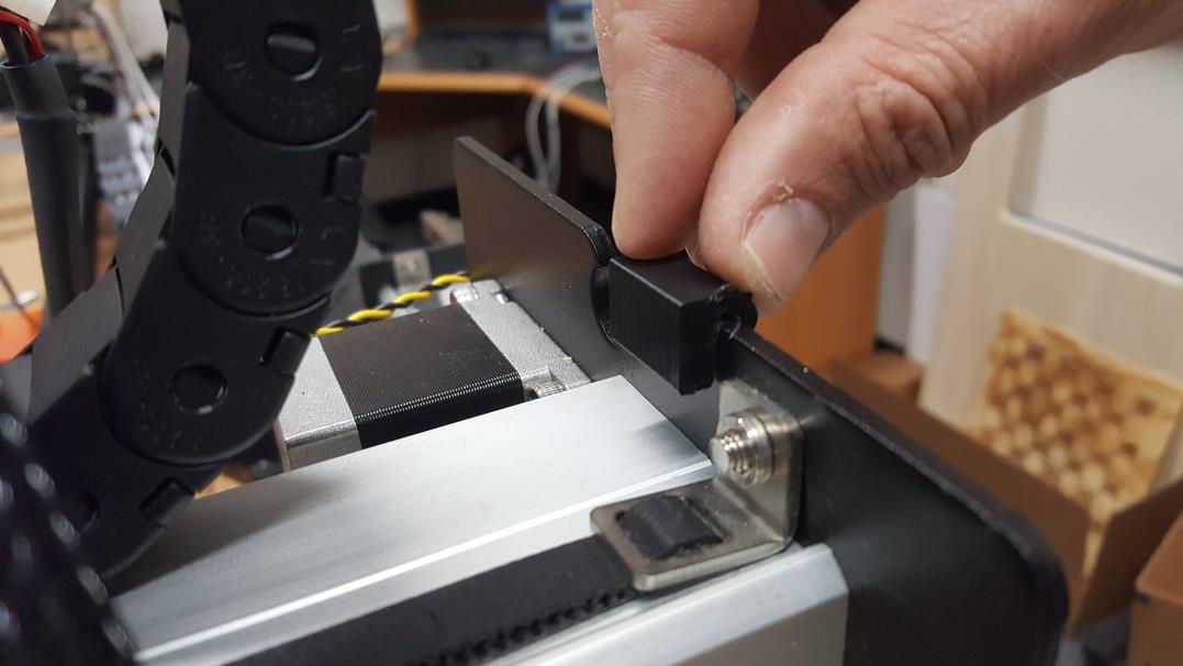
This will allow for the laser not to hit the side when homing.
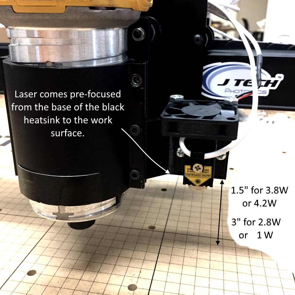
Step 8: Focusing the Laser
If you purchased the laser shroud, then your laser came pre-focused to 1/8″ above the work surface.


If you did not get the shroud, then the focus is set to the bottom of the base of the black heatsink.
Now you are ready to start creating!
Step 9: Running the Laser
We recommend using lightburn software with your machine to control your laser. How to set up the software is located here:
If you rather use the Free tools like the inkscape plugin we have, then you will need a sender program. You can’t use carbide motion, as it creates a delay with the spindle command, which will give you dots where the laser turns on and off.
There are a lot of different “sender” programs that will work with your machine. In the inside of your machine is something called “GRBL” that directs how the machine moves and interprets the G Code file. The G Code file is the “instructions” and GRBL just needs some program to “send” it to the GRBL that is in the firmware of your control board.
Here is the wiki page with all of the sender program available:
http://www.shapeoko.com/wiki/index.php/Communication_/_Control
We like to use the “universal G Code sender” as it is the standard for the previous shapeoko machine and has a very large user base. It is located here:
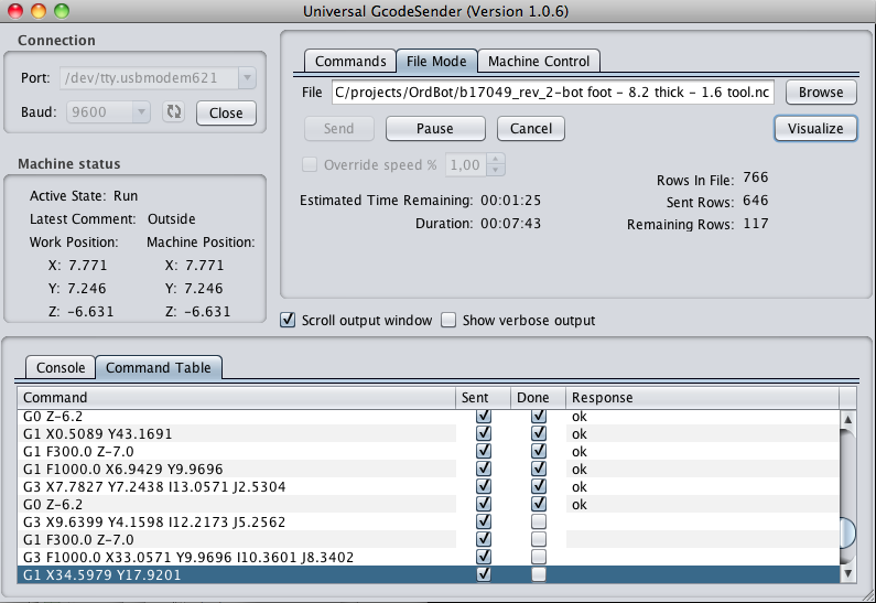
Here are some instructions on running the shapeoko3 with Universal G Code Sender:
Universal G Code Sender Basics Tutorial
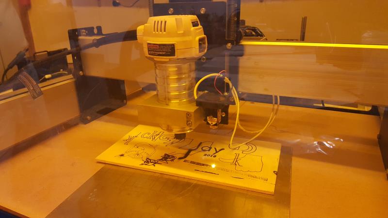
Using the Router
When you are finished using your laser, simply unplug the laser cable and the fan cable from the extension cords and remove the laser from the magnet base plate. Then, make sure your router is pushed all the way down in the aluminum spindle mount so the laser mount is not in the way. The chuck will be about 1″ under the bottom of the laser mount and will not interfere.


BUY YOUR Laser and Mounting Kit HERE!
Remember Safety First!

We sell laser shielding to block laser radiation and reflections!

Laser Goggles are also a must!
Disclaimer
The laser used in this project is very powerful and all safety precautions must be taken. Use proper safety eyewear to prevent injury to eyes. This is a project and J Tech Photonics, Inc. is not responsible or liable for any and all damage or injury caused to people or property. The use of these instructions to make a laser cutter is under your own discretion and all safety precautions should be followed. J Tech Photonics, Inc. is not affiliated in any way with ShapeOko or Carbide 3D and they may change hardware and software at any time making these instructions invalid.
Is there a similar kit & description for the Shapeoko 3 Sparkfun Edition – with the Sparkfun Stepoko controller board?
If you have a desire to learn how to earn from $ 500 per day and work only for yourself, then write to us at email: [email protected]
I recently put a laser on my shapeoko.
The laser work is so great.
But I have a problem when using shapeoko with carbide3d.
Only the rapid position button is recognized and the x,y,z movement buttons do not work.
Is there any solution to this phenomenon?
Hey there I’m looking into buying one of these laser, do you guys have a timeline on when it will be a available for the Shapeoko 4?
Will this laser with Shapeoko xxx do small pen blanks?
WHICH MODEL LASER WILL CUT 1/8″ THICK WALNUT OR CHERRY OR MAPLE. I HAVE A SHAPEOKO XL WITH DEWALT ROUTER.
Watched the videos and I’m curious what controls the stepper motors on the shapeoko when using the laser
Thanks,
Darren Roe
your instructions need to be upgraded for the newer 3xxl kits. There is only one white cable and one black cord.
Hi, I just replaced a fried Shapeoko 3 board and need a press fit pwm/gnd connector. Please correspond with ordering instructions.
Thank you for your excellent product lineup!