


The MakerGear M2 printer is the top selling 3D printer on Amazon.com and it is their 3D generation of their printers so it comes with great accuracy and build quality. That being said, what if you want to put a laser on it? Good question! These are the instructions on how to get the M2 set up with the electronics to control the laser driver board via G Code.
The M2 uses the Rambo board from the RepRap project (info here: http://reprap.org/wiki/Rambo). The board has two fan outputs as well as a header for accessory PWM outputs. Considering it has a nice header for the PWM outputs, I think this is the way to go.
Of course, you will still need to figure out a mechanical design to mount the laser to the printer Z axis, but that should be a fun project on the printer! The dimensions and solid models are located in the documents section of the website.
I know everyone is anxious to here how this will work, so let’s get started!
Electrical Connections
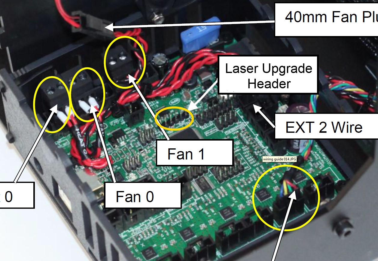
You will have to remove the top of the electronics box to get to the Rambo board. The header for the PWM signals are just right above the processor chip in a single row called “PWM EXT”. There are 6 pins, starting with pin 1 on the left. A picture is shown below where the header is. It is labeled “Laser Upgrade Header”.
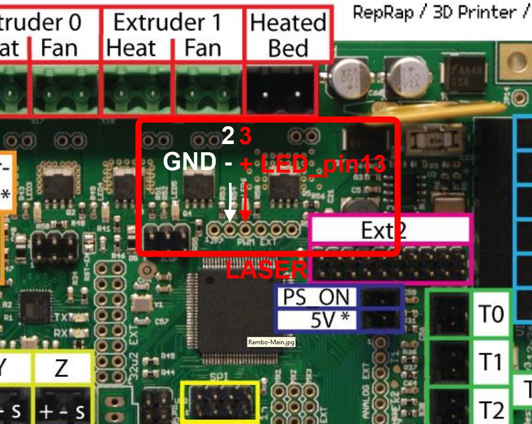
The M2 has the feature to add an LED to the printer, so we are going to use this output. There are two of the pins that are needed to connect to the laser driver board:
- Pin 2 = GROUND . Use this to connect to the “-” input on the laser driver board.
- Pin 3 = POSITIVE. Use this to connect to the “+” input on the laser driver board.
This is shown in the following picture:
If your board has a header on it, then you can either solder a wire to it, or you can get a cable here at Sparkfun (https://www.sparkfun.com/products/8672).
Firmware and G Code
The Marlin firmware has included in it a method for controlling the pin 13 LED signal to be able to turn it on and off with PWM. The command is “M42 P13 SXXX” where XXX is a value between 0 and 255 for the power level. Examples of some commands would be:
- M42 P13 S255 = Turns the laser on at full power
- M42 P13 S0 = Turns the laser off
- M42 P13 S127 = Turns the laser on at 50% power
So, when you make a program file, just replace the “M03” code with “M42 P13 S255” to turn the laser on and replace “M05″ with ” M42 P13 S0″ to turn the laser off.
Then run this file in the software of choice (including in simplify3D) and get lasering!
Buy your laser upgrade kit now!

Remember Safety First!

We sell laser shielding to block laser radiation and reflections!
Laser Goggles are also a must!
Disclaimer
The laser used in this project is very powerful and all safety precautions must be taken. Use proper safety eyewear to prevent injury to eyes. This is a project and J Tech Photonics, Inc. is not responsible or liable for any and all damage or injury caused to people or property. The use of these instructions to make a laser cutter is under your own discretion and all safety precautions should be followed. J Tech Photonics, Inc. is not affiliated in any way with MakerGear and they may change hardware and software at any time making these instructions invalid.
Is the M03 code the same as M3?