
MakerMade is now offering a laser upgrade to the popular M2 CNC platform. You can purchase it here:
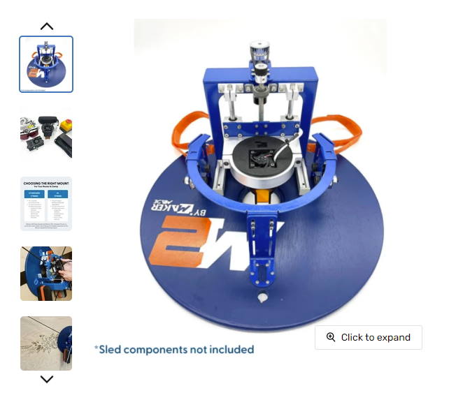
Setup Instructions
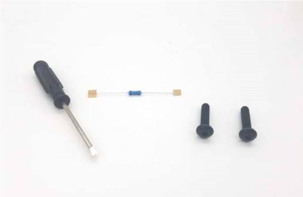
Tools and Hardware Required
- Small Mini Flathead Screwdriver (included)
- M3 Allen Wrench for 71 mm clamp, or M5 Allen Wrench for 91 mm clamp
- 2 – 25 mm M3 screws to use with the 71 mm clamp (included) • 1KhZ resistor (included)
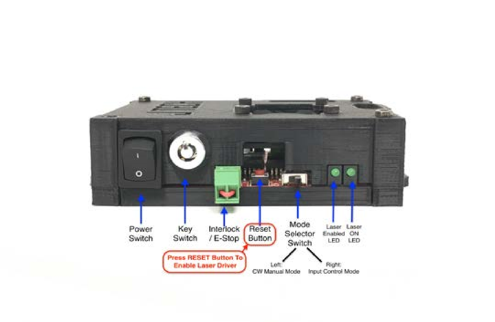
Laser Diode Driver Diagram
1. Attach the Laser Mount
Loosen the router clamp and remove the router.
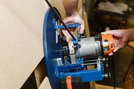
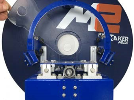
Remove the clear plastic dust channel cover.
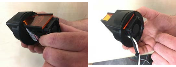
Insert Laser Module Into Laser Mount
*for 71 mm mount: Remove exsisting clamp screws and insert the laser mount. Use the longer 25mm screws provided to secure the mount into the clamp.
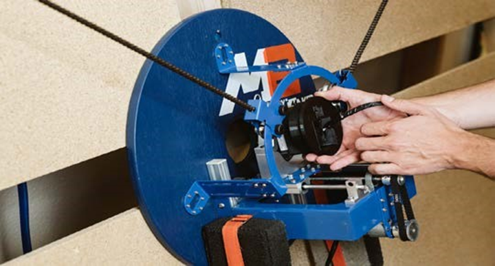
Insert Laser Mount Into Router Clamp. Tighten Clamp.
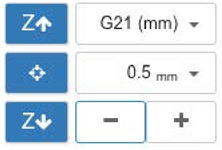
Use the Z-Axis controls in the Controls widget in Makerverse to move the Z-Axis toward the work surface until the laser shroud is 1/8” above the work surface.
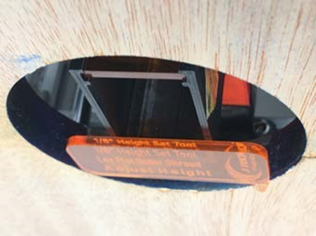
Use the focusing tool provided in the laser kit to make sure the laser shroud is 1/8” above the work surface.

You can do this by tilting the sled back slightly to slide the focusing tool behind the sled. The focusing tool should be flush with the bottom of the sled.

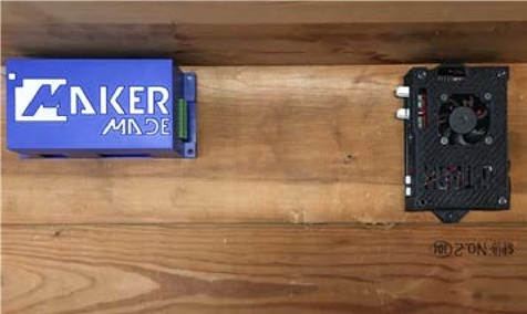
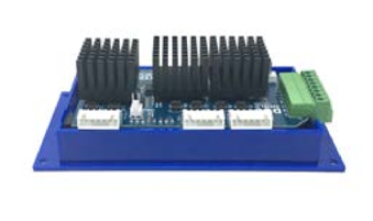
2. Mount the Laser Driver
Mount the laser driver close to the M2 control board.
You can use the sticky pads to attach the laser driver near the M2 control board or you can mount it using screws.
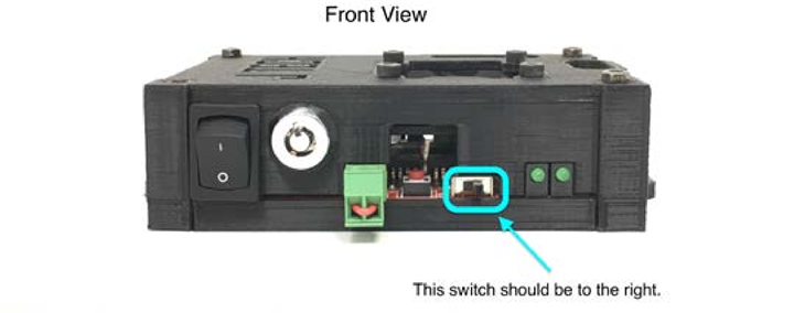
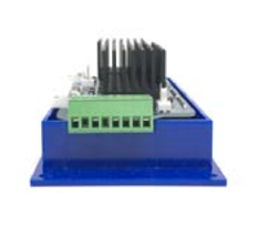
Make sure the Mode Selector Switch on the front of the laser driver is to the right. (Input Control Mode)
3. Run the Laser and Fan Extension Cables
The two cables in the mounting kit are the Laser Extension Cable (thicker cable) and the Fan Extension Cable (thinner cable).
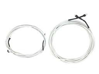
Find the female end of each You can put a small piece of tape extension cable. on the ends to keep them together.
Feed the female ends of the extension cables down behind the frame and pull the extension cables out far enough to attach to the sled.
4. Connect the Laser Driver to the Control Board
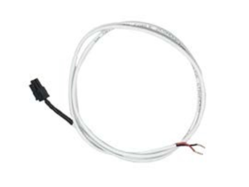
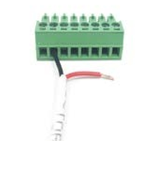
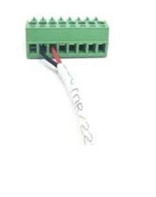
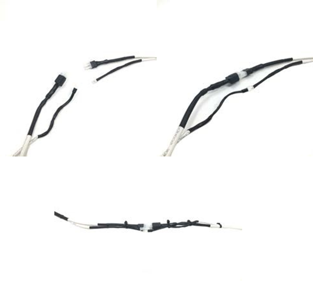
Find the Molex Mini Fit Jr. Input cable. (pictured below)
On one end is a black connector. On the other end are two wires.
The BLACK wire is the Ground.
The RED wire is the PWM or spindle speed control.
These two wires will connect to the M2 control board.
Remove the case cover from the M2 control board.
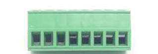
Find the green connector on the M2 control board.
If it makes it easier, you can remove the green connector plug from the motor shield by gently pulling it straight out.
Loosen the screw in the 1st position Labelled 12V.
Loosen the screw in the 2nd position Labelled GND. Loosen the screw in the 3rd position Labelled LSR.
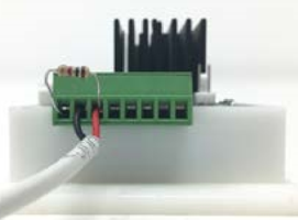
Insert the BLACK wire from the cable into the 2nd position on the green connector labelled GND. Tighten the screw.
Insert the RED wire from the cable into the 3rd position on the green connector labelled LSR.
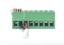
Insert one end of the 1K resistor into the 3rd position on the green connector labelled LZR. Tighten the screw.
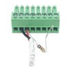
Insert one end of the 1K resistor into the 1st position on the green connector labelled 12V. Tighten the screw.
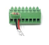
When you have done that, the green connector should look like below.
If you removed the green connector plug to make these connections, snap it back into the motor shield.
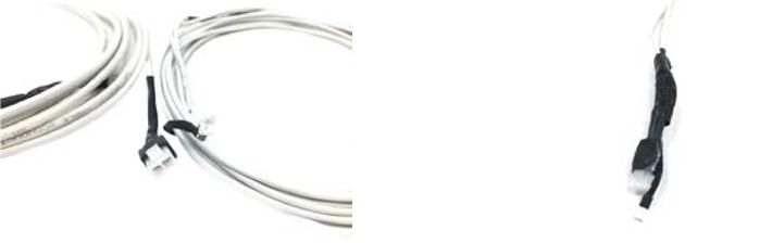
The other end of the cable you just connected to the M2 control board will have a black Molex connector on it.
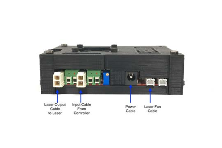
This black connector goes into Terminal H4 on the back of the laser driver. (Input cable from controller)
Terminal H4 may have a black dot or line on the driver connector. (see picture)
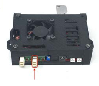
Double check to make sure this is correct. You can cause damage to the laser driver if the cable is not plugged in to the correct terminal.
6. Connect the Laser Cable to the Laser Driver
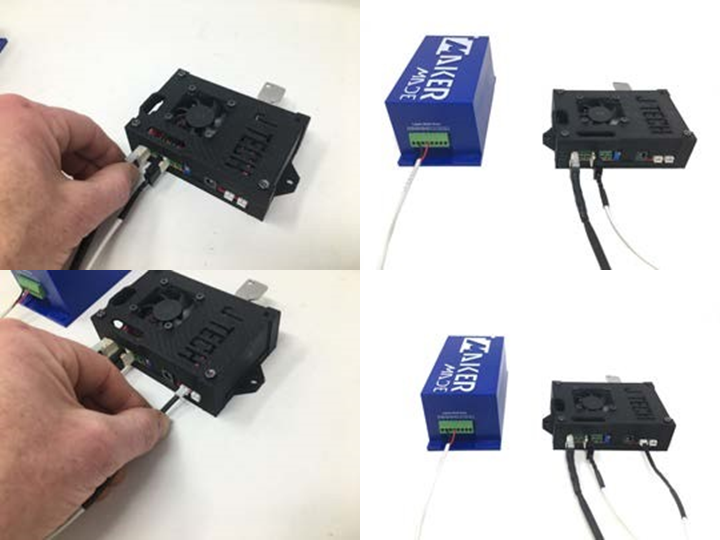
Find the opposite end of the extension cables you fed under the frame with the male connectors.
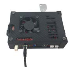
Connect the thick laser extension cable (with the clear end) to the laser driver board in Terminal H3. (Laser Output)
Connect the thin fan extension cable to the laser fan connector on the driver board.
7. Connect the Laser to the Extension Cables
Connect the laser and fan cables to the extension cables.
Ensure you have enough slack so the extension cables will be able to move freely as the sled moves around the work space.
Use zip ties to keep laser and fan extension cables neat and together.
8. Connect Emergency Stop Button (Optional)
Connect E-Stop Cable to green connector on front of laser driver.
*Please Note:
Laser will not work without the included jumper OR E-Stop connected.
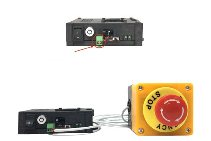
To reset the E-Stop, twist the red button to the right and the button will pop up.
Your Laser is Now Assembled!
The next step is to get started engraving projects with LightBurn and
Makerverse. You can find our LightBurn configuration guide on the laser resource page on our site at makermade.com/laser-resources.
Have a question or need guidance?
The MakerMade technical team is available to help! You can fill out a support ticket at: https://makermade.freshdesk.com/support/tickets/new