


The folks over at Onefinity have made a truly amazing new machine with linear rails, integrated controller, and the ability to rapidly take apart and move the machine. We have been working with them for years on the Suckit line of products, so it was easy for us to partner with them to provide a new laser solution for their machine.
Lets get going on how to get this installed!
Installation Video Standard Machine
Installation Video Elite Series Machine
Lasers Available for Purchase

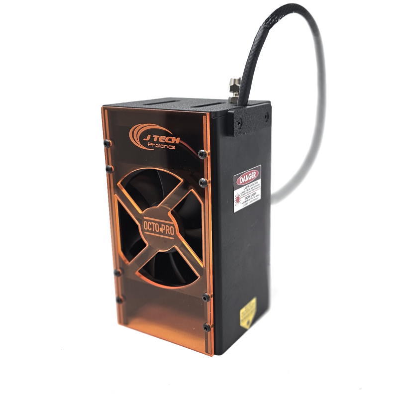
And the all new 64W!

All of the lasers offered work with the new Safety Interface Module and the new locking mounts. If you purchase a laser kit from Onefinity, you can purchase any of the other laser heads and it will work with the SI module, cables, and mount.
All Laser Kit Contents
The laser kit will contain:
- Laser Head with High Resolution Lens
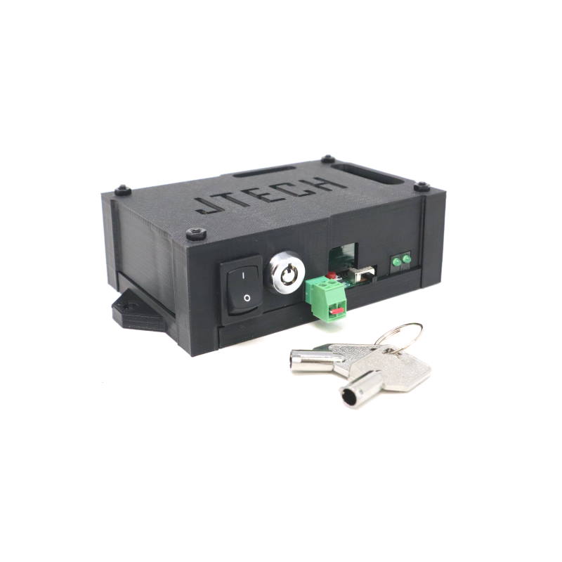
- Safety Interface Module with Key Switch and other Safety Features
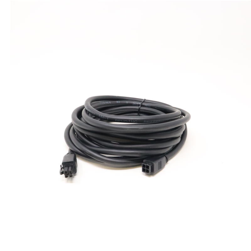
- 15′ Molex 4 Pin Black Extension Cable
- Onefinity Laser Input Cable
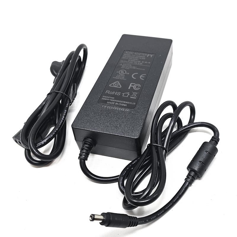
- Power Adapter fit for the Laser
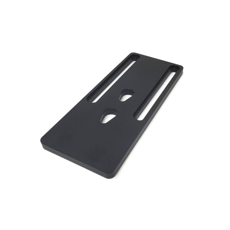
- Onefinity Magnet Locking Laser Mount
- Laser Goggles
- Focusing Tool
- Zip ties and zip tie holders
- SI module mount for the Masso Controller (not needed on the Classic machines)

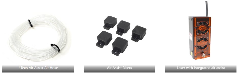
The 24W, 44W and the 64W additionally come with:
- Integrated Air Assist Nozzle
- 12′ or air hose
- Material riser blocks (small black plastic blocks to lift your material)
Wiring the Safety Interface Module
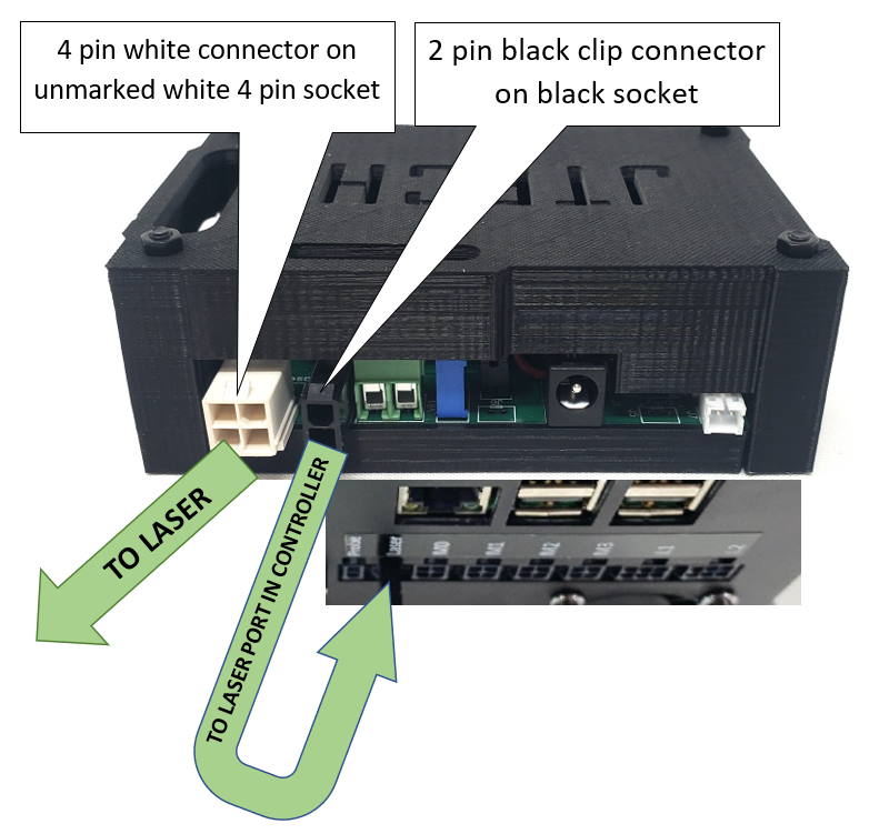
If you have the classic machine, then the Safety Interface Module will go on top of the black control box. There are screws on the controller you can use to attach the SI module to the top. You then can connect the small black Molex cable to the black connector on the back of the SI module. Put the other side to the “laser” input on the Onefinity controller. The long laser extension cable will connect to the 4 pin white Molex connector on the end of the SI module.
The extension cable will go up to the Z gantry routed along the Axis to make sure they are not caught in the linear rails.
Enabling the SI Module – The Red Reset Button
To enable the driver you need to follow a sequence for safety. There are two safety features required by the Federal Government that you will need to know about. The key switch and the red reset button. Here is the sequence you need to follow to turn the laser driver on.
- Plug in the power adapter to a known good outlet. You should see the LED on the power brick turn on.
- Put the key into the laser driver and turn it to the right.
- Press the red reset button. You should hear a slight “click” with the interlock engaging.
- Turn the power switch on by pressing in the “|” mark. Your fans should turn on and you should have one led on.

Mounting the Laser
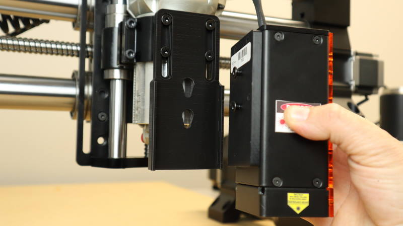
Attach the mounting plate to the front of your router/spindle holder on the Onefinity machine. You can adjust the mount up and down by setting the height and then locking the all four M5 screws that hold it to the router/spindle holder.
The lasers will connect to the mount with two screws that will latch it in place. Put the laser onto the mounting plate and then push down to secure it. You can tighten the screws to increase the tension on the mounting plate or you can lock it in place permanently if desired. You want the back screws to be adjusted so that you get a snug fit on the mounting plate.
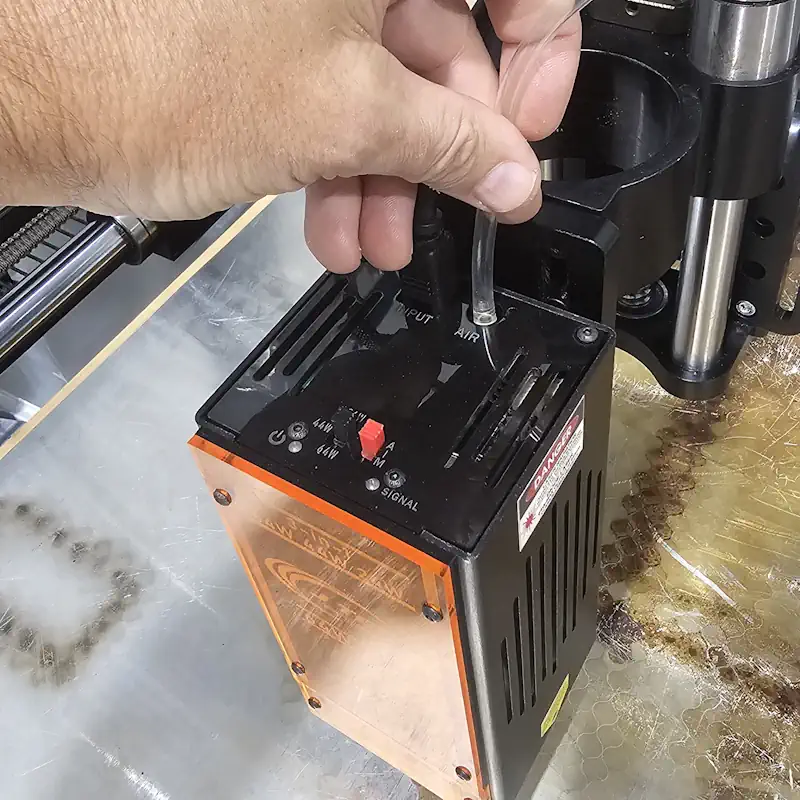
Air Assist Connection
If you have the 24W, 44W, or 64W lasers, then they came with an included air assist nozzle. The 24W has it in the front of the laser. The 44W and 64W have the connection on the top of the laser. Make sure you have the air assist hose connected and use a sufficient pump (55W or greater) when using the laser.
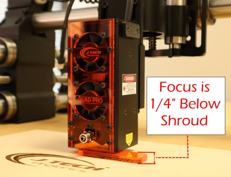
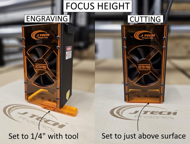
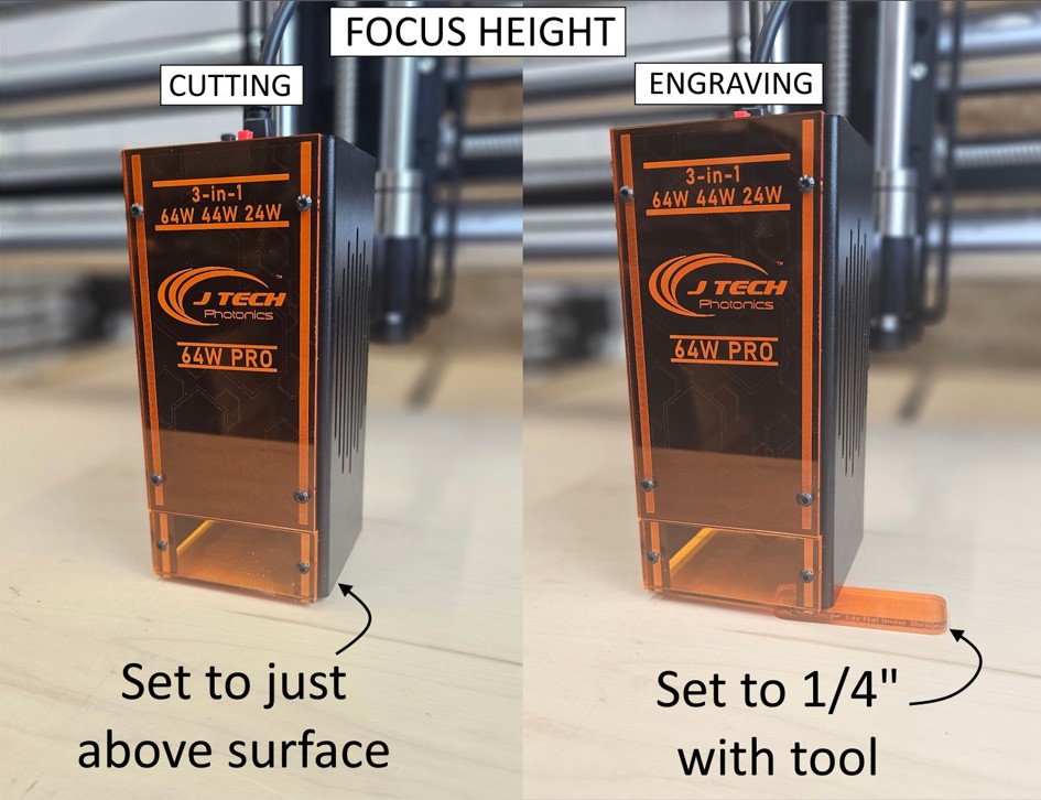
Focus for Engraving versus Cutting
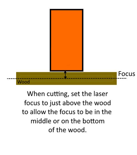
The laser should be focused depending on what application you are completing. In the case of engraving, the laser should be focused on the top of the wood using the focus tool.
For cutting, we recommend putting the focus at the middle or the bottom of the material. For example, if you are cutting 1/8” material, then set the focus of the laser at 1/8”. If you are cutting ¼” material or more, then put the laser almost touching the material to allow for the focus to be at the bottom.
You can see the examples of the different tools for the lasers below.
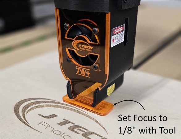
7W+ Version
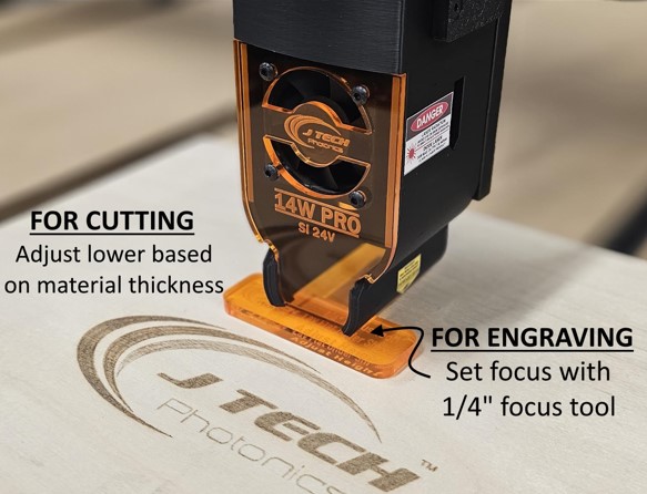
14W PRO SI Version
24W Focus for Engraving
For cutting with the 24W, put the focus closer to the material based on the thickness.
44W Focus
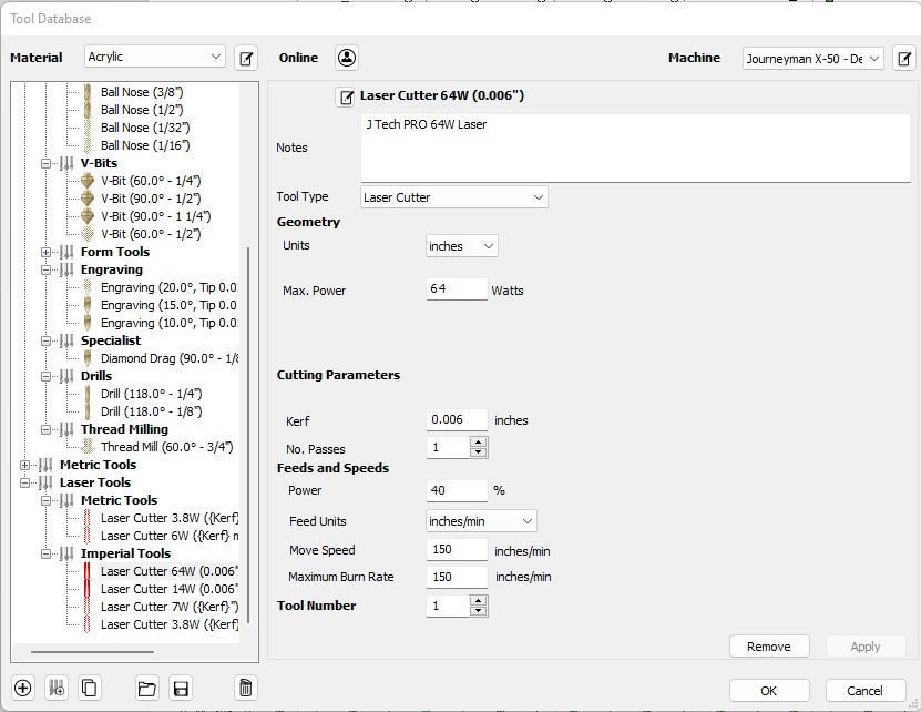
64W Focus
Setting Up the Classic Controller
Select the “Tool” option in the menu of the controller. (Three horizontal lines in upper left of display.)
If you have the newest version of the firmware, then select the “J Tech Laser” option. Click on the “Save” button on the top to save the configuration.
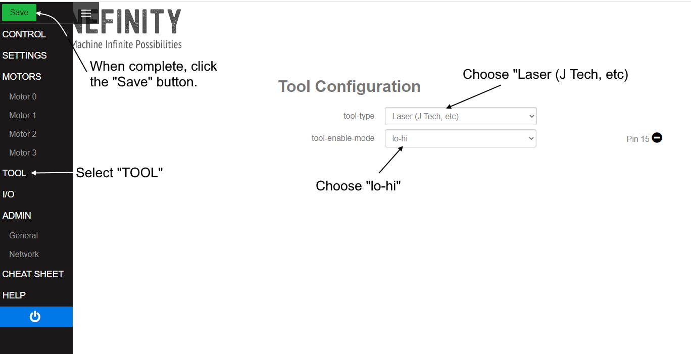
This should work for all of the newest firmware versions and you are done. If you have a previous version of the firmware that does not have the J Tech Laser option, then do the following:
For use with the J-Tech laser this needs to change to “PWM Spindle” with the following settings.
- Max-spin = 1000
- tool-enable-mode = disabled
- tool-direction-mode = disabled
- rapid-auto-off = enabled
- dynamic-power = enabled

Firing the Laser in Low Power (Classic Controller)
For the Classic Machine controller, you can use the MDI tab to fire the laser in low power. Because every machine is different, you may need to adjust your low power setting. You can use the MDI to fire the laser low enough power to see the spot, but not burn the material.
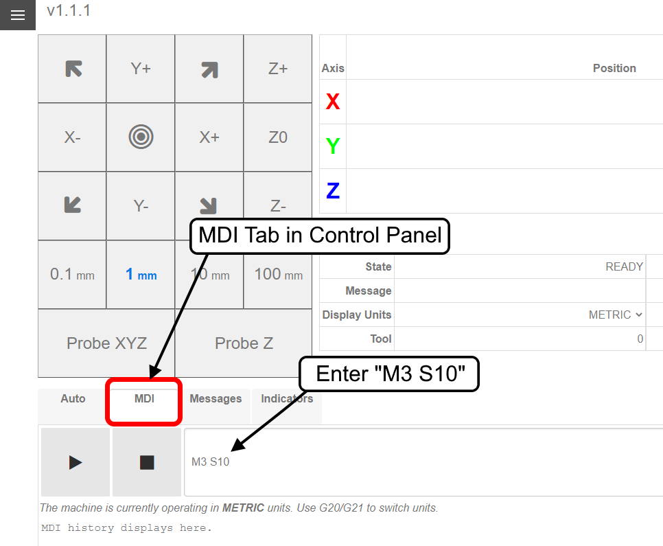
Prepare your laser head to adjust the input power by moving it to an area with a scrap piece of material and put it up high in Z so it is not in focus. In the Onefinity MDI, type in a low power command of M3 S10. We recommend setting this low power to about 1% for this adjustment. Press the “play” button to fire the laser.
If this is not firing the laser, then try a larger number in sequence until it turns on. Start with M3 S11, then M3 S12, and so on until you get the laser to fire.
If it is firing in M3 S10 and it is too strong, do the opposite and go down in numbers until it just turns on. Do, M3 S9, then M3 S8, and so on until it just fires low power.
Write this number down as you will use this to set your zero for your projects.
Lightburn Setup for Redline Controller
Setting Up the Elite Machine for Laser (Masso)
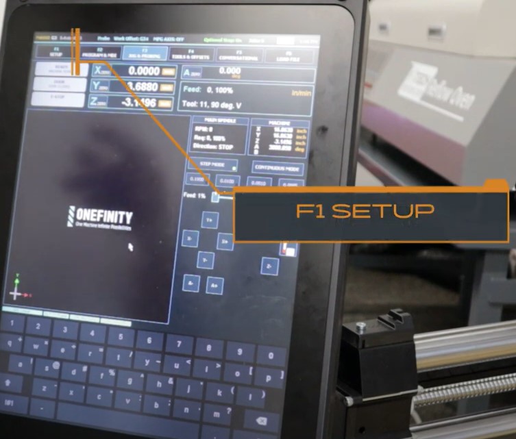
We are going to walk through the setup procedure found in the video to make the Masso controller accept a laser input.
- Press the F1 “Setup” button to enter the setup page.
When it prompts for a password, the password is just blank. Hit the enter key to continue.
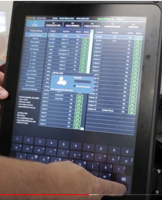
After you get through the password, click on Output 11.
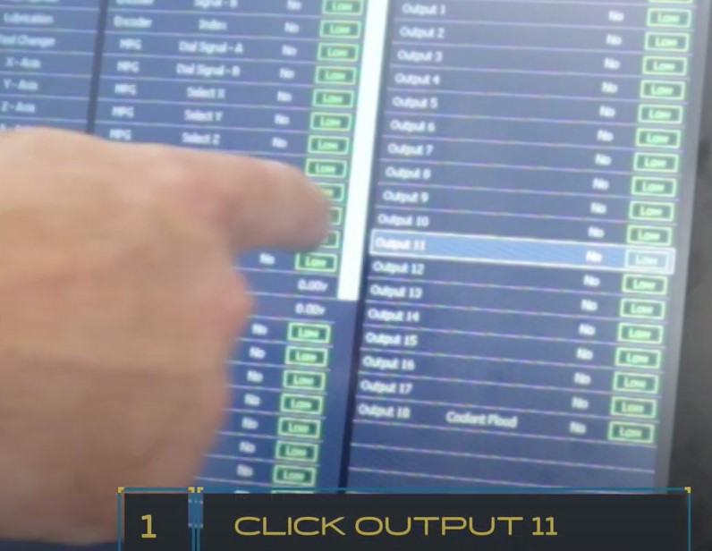
Change Output 11 to “Laser Engraving (PWM)”.
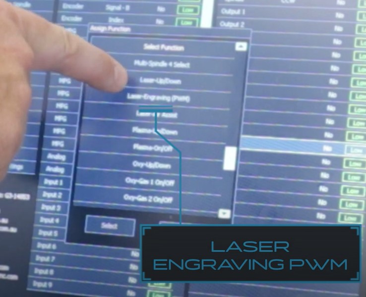
On the left of the screen, click on Multihead. A pop up will come up.
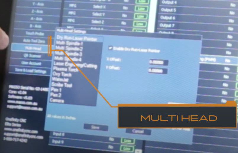
Under “Laser Engraving/Cutting” set the PWM to 4000.

This sets up the laser tool in the Masso controller.
Changing to the Laser Tool on the Masso
Once you have your laser tool set up, you can change to it by doing a tool change. Enter the MDI so you can make the tool change to laser.
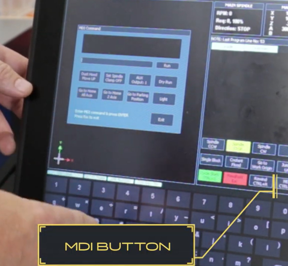
Here is where you can enter in codes to change tools as well as fire the laser in low power. To change the tool, enter in “T111 M6”.
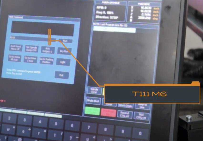
This will now show up in your tool box.
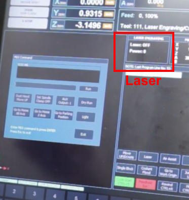
To change back to a spindle tool, you can type “T1 M6” or whatever tool number you want. T111 is reserved for laser though.
To put the laser in low power mode to find your position to zero your project, you can type in the MDI the command M3 S10 and press run. This should turn the laser on in low power.
If this is not firing the laser, then try a larger number in sequence until it turns on. Start with M3 S11, then M3 S12, and so on until you get the laser to fire.
If it is firing in M3 S10 and it is too strong, do the opposite and go down in numbers until it just turns on. Do, M3 S9, then M3 S8, and so on until it just fires low power.
Write this number down as you will use this to set your zero for your projects.
Setting Up Vectric for Lasering
Using the laser in Vectric software is as simple as getting a new post processor. If you don’t have the new laser module plugin, just set up your laser as an end mill. If you do have the new laser module plugin, then put the laser as a laser tool. Here is how to set up both.
For the Non-Laser module users. Follow this link on how to set up the post processor and your tool:
For the laser module users, follow this link to set up your post processor and your laser tool.
The 7W laser tool will be set up like this:

All you need to do to create your laser file is to generate your laser toolpath with the onefinity laser post processor.
The 14W Laser will be set up like this:
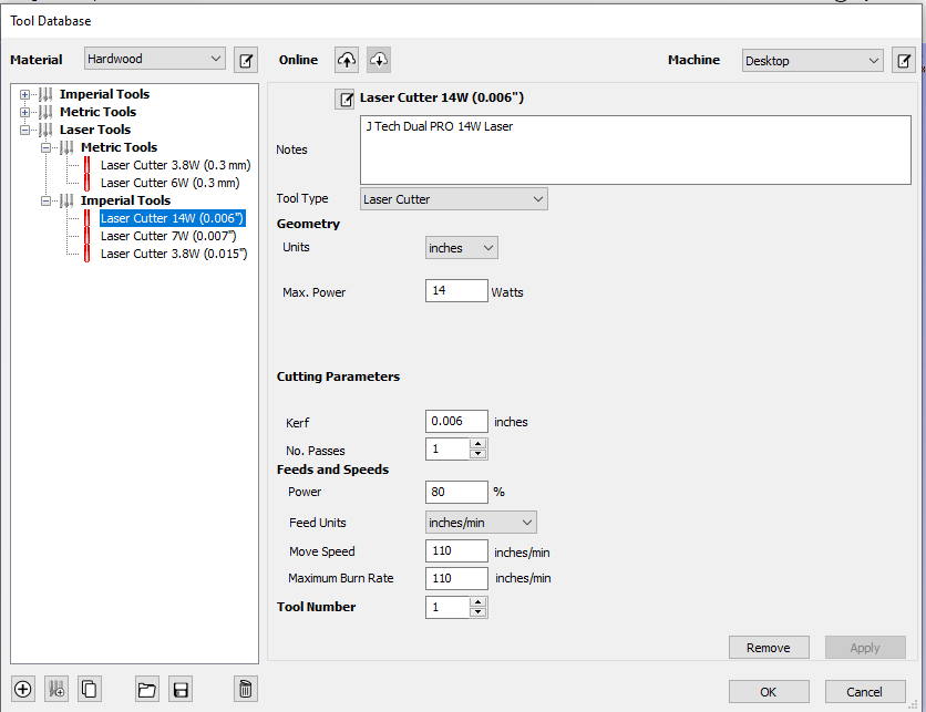
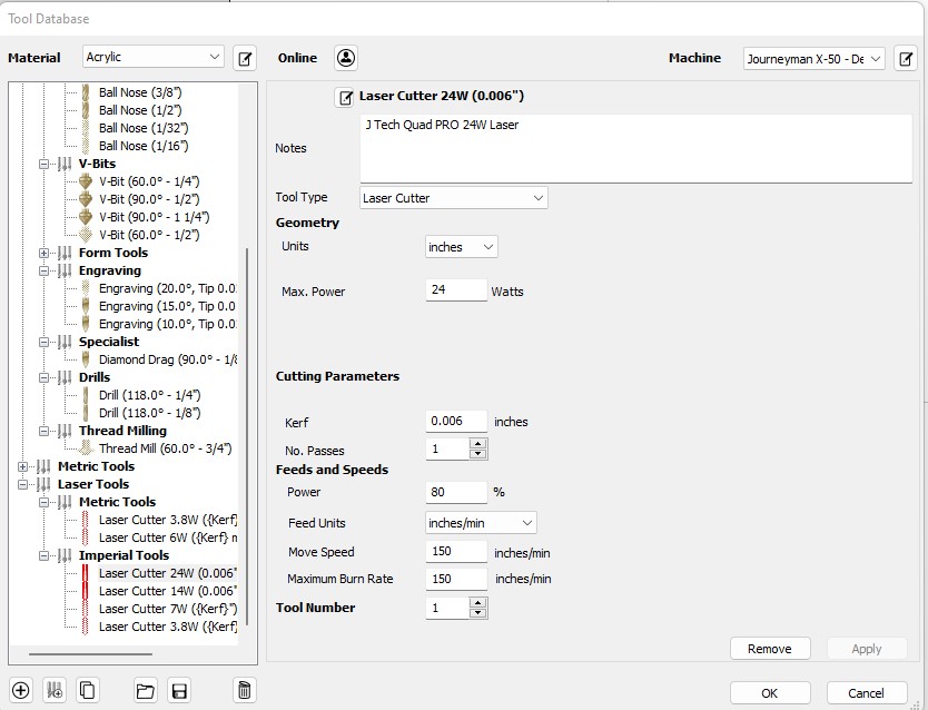
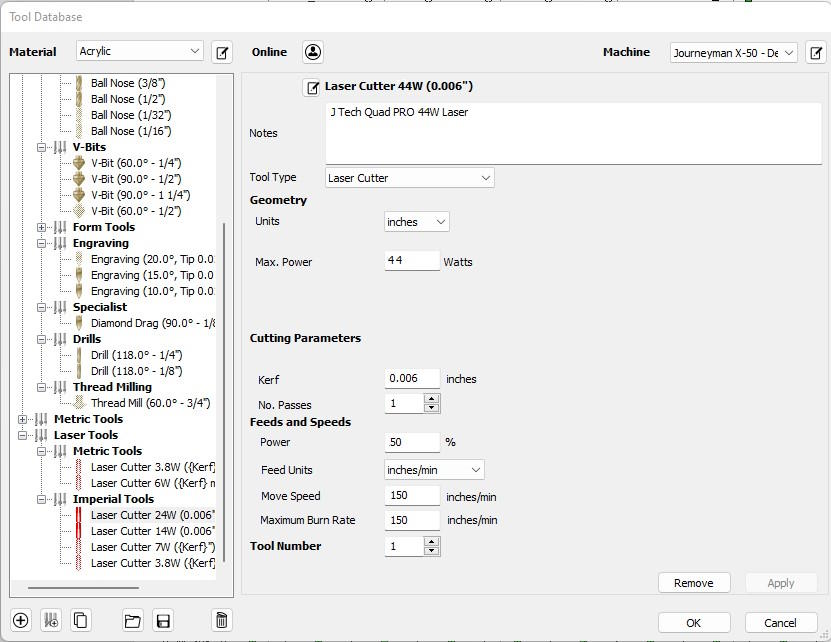
The 24W, 44W, and 64W will be like the 14W, but you can increase the speed when engraving or lower the power.
The speed and power will need to be set for your desired depth of engraving, darkness, and look. The slower you set it and the higher the power the darker and deeper it will engrave. The faster you set it and the lower the power the lighter and less deep it will engrave.
For cutting, you need to go slower, but not less than 10 inch/min per pass. On all of the lasers when cutting, be super vigilant as there is the possibility of flare up of the material. Never leave the machine unattended.
Setting Up Lightburn
Lightburn is an all in one laser program that does pictures and vectors in the same program. It is very functional and easy to use. You can download a free trial or purchase it here:
 Download Lightburn Software HERE
If you choose to use LightBurn, then here is how to set it up.