


These are the instruction on how to add a J Tech Laser to your BOBs CNC machine. Bobs CNC machines are very simple, cost effective, and popular for new CNC enthusiasts. We purchased one about 6 months ago and have developed a laser kit for it. Here are the instructions on how to set it up. But first…
*Disclaimer*
All instructions for upgrading machines are all done at the buyers or viewers own risk. Lasers are inherently dangerous and all safety measures are the responsibility of the buyer or viewer. While we provide some safety features on our laser kits, it is not a complete laser machine, so all additional features are up to you when you build your machine including interlocks, fume extraction, and fire prevention. Any company or machine mentioned in this webpage is not associated with J Tech Photonics Inc. and they in no way endorse these instructions.
Ok, now that we are done with that part, lets move on.
*These are the BETA instructions*
If there are any mistakes, please let us know at [email protected]
Overview
We have made an “all in one” bundle for the Bobs CNC machine to make it easy to order. You can located it here:

Purchase the Bobs CNC Laser Upgrade
The laser upgrade is pretty simple and consists of the laser and the laser driver board and the mounting kit. In the mounting kit we have:
- Laser Quick Connect Magnet Mount (2 piece)
- Mini Molex Jr. Input Cable
- Mounting Screws
- Driver Mounting Sticky Squares
- 10 foot Laser and Fan Extension Cables
- Zip Ties and Zip Tie Holders

Now let’s discuss how to set it all up!
Mount the Laser
Step 1: Assemble the mount
The mount comes with two pieces and two sets of M3 screws.
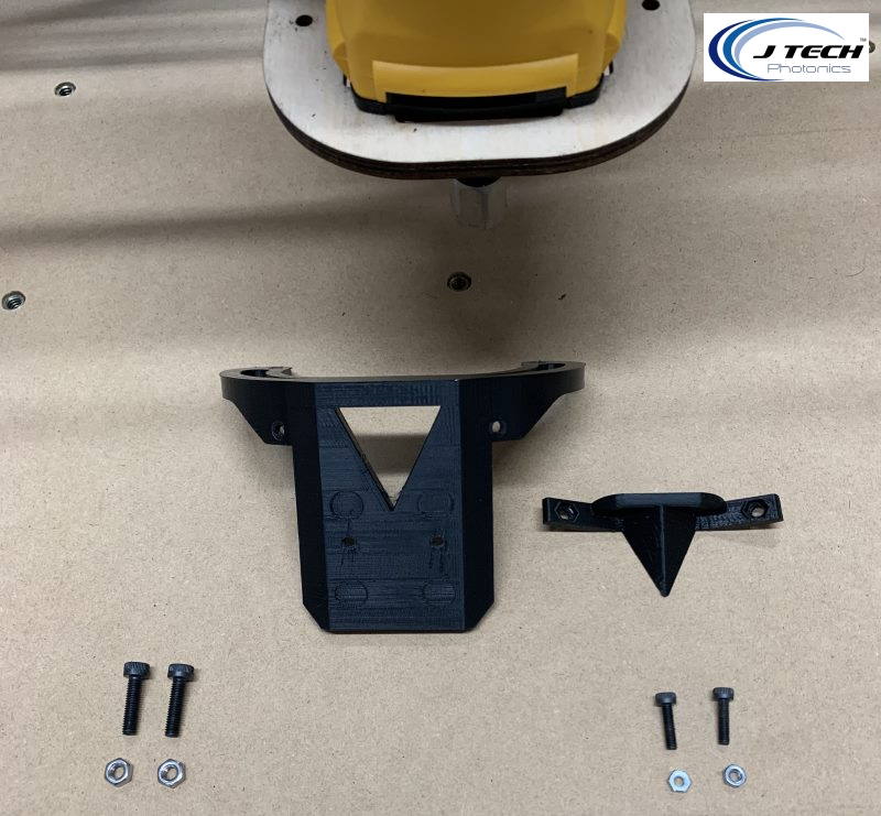
Place the smaller plastic piece on the back of the larger mount like in this picture:
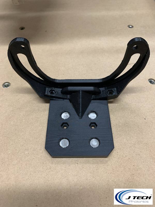
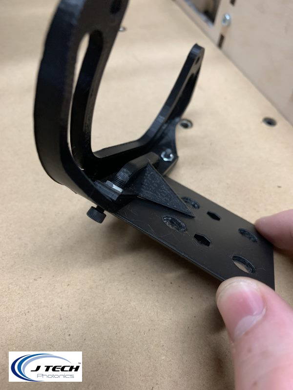
Use the smaller set of M3 Screws to mount the smaller back plate to the larger front plate. Leave these slightly loose. It will look like the following:
Step 2: Attached the mount to the Gantry
Slide the mount onto the front of the gantry plate.
Place the larger Screws through the holes of the mount and machine. Do this on both sides and leave loose.
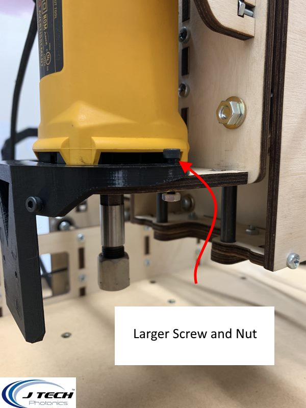
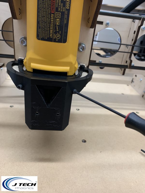
Tighten the smaller screws in the font making sure the mount is fully seated. Then, tighten the larger screws in the back.
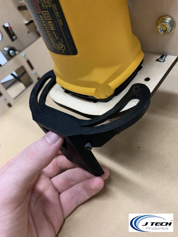
Step 3: Attach Laser
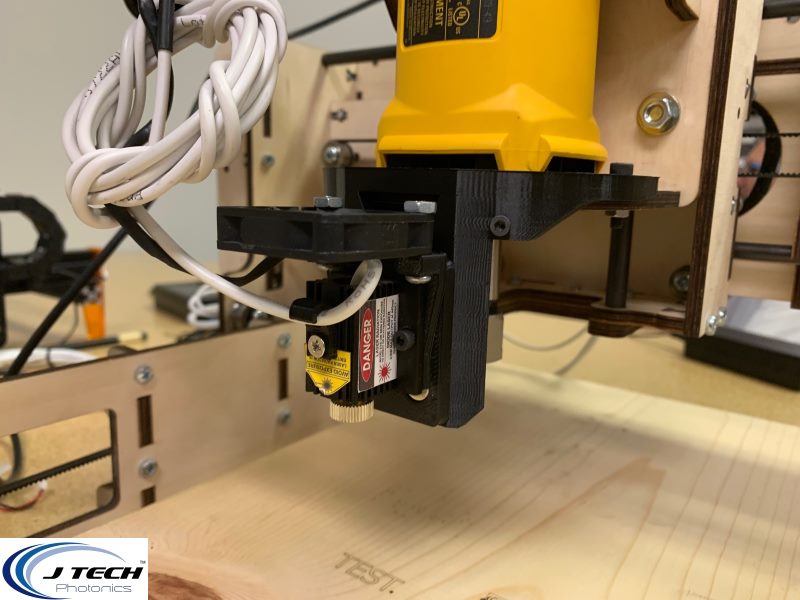
If you purchased the magnetic shroud, then place the laser on the magnet mount being careful to line up the small alignment screws with the holes in the mount.
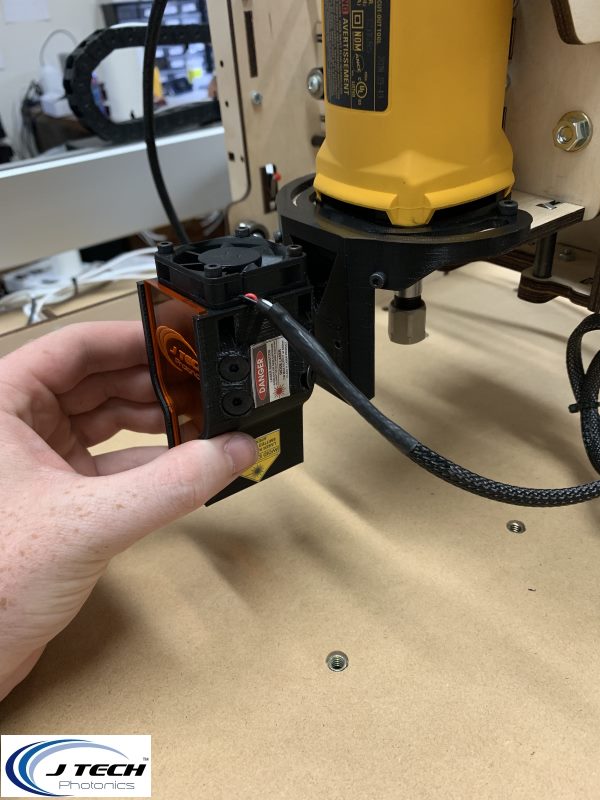
If you didn’t purchase the shroud, then it will look like this:
Wiring
This is a simple process and there are only two main tasks that need to be completed
- Mount and Connect the extension cables the laser and the driver
- Mount and connect the PWM and the GND to the controller and the driver
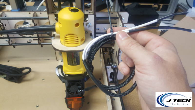
Step 4: Zip tie the end of the laser and fan extension cables
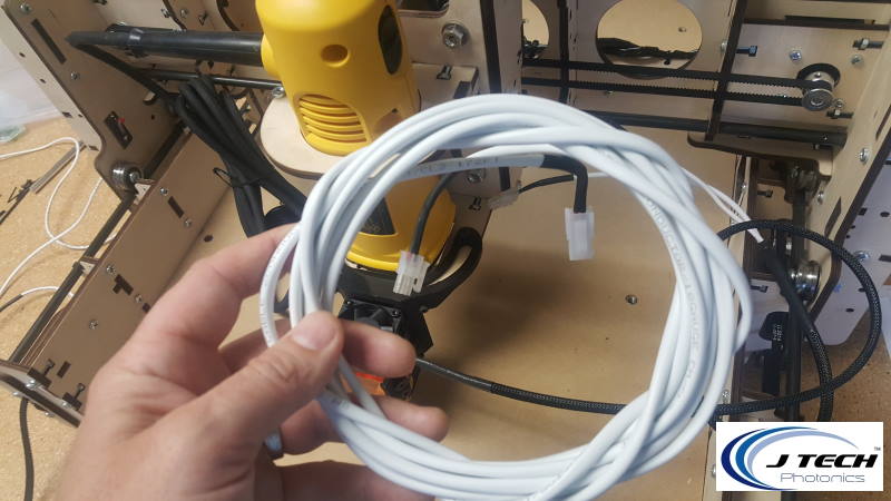
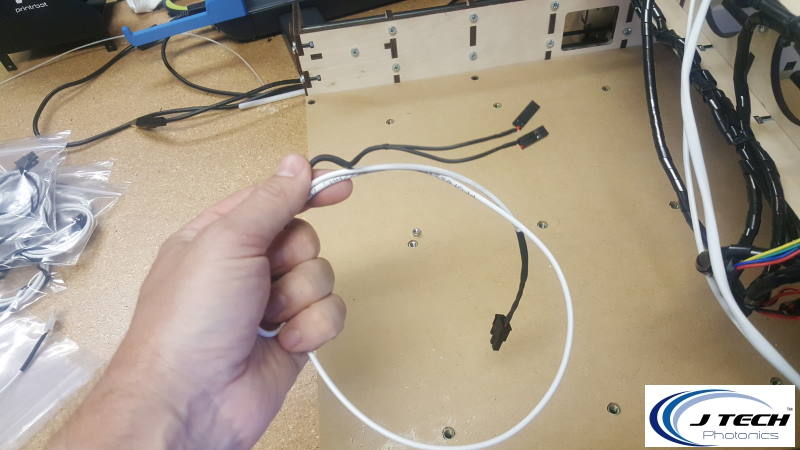
Grab the extension cables from the bag and get them ready by unrolling them.
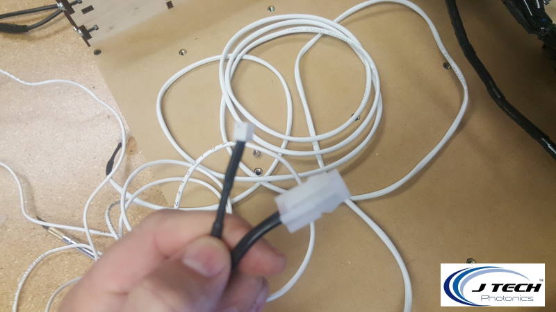
Get the female ends of both of the cables ready.
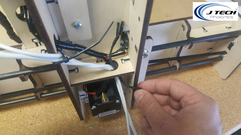
Use one of the zip ties from the mounting kit to put in the back of the Z stage gantry a loop for the cables to go through.
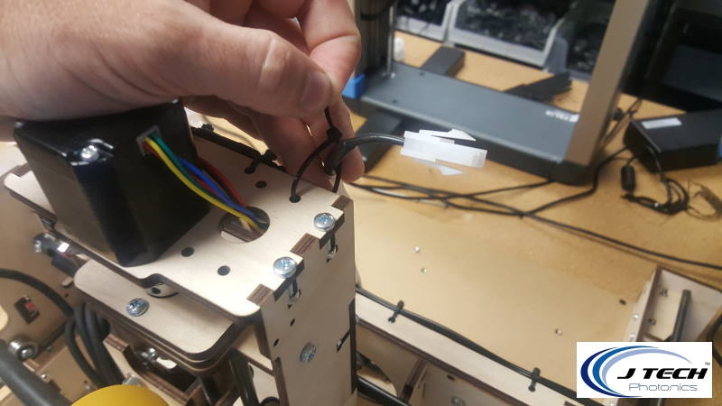
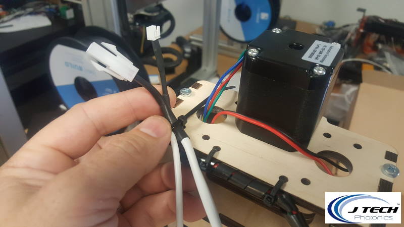
Put both the laser and fan extension cable female ends in the zip tie loop and tighten them down.
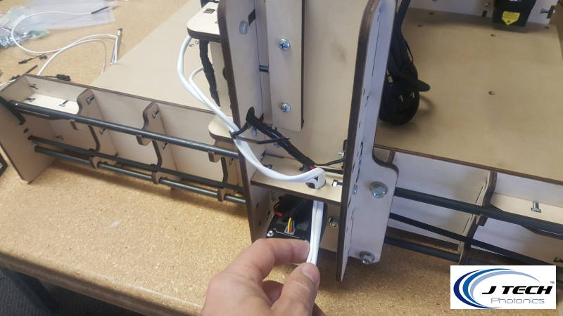
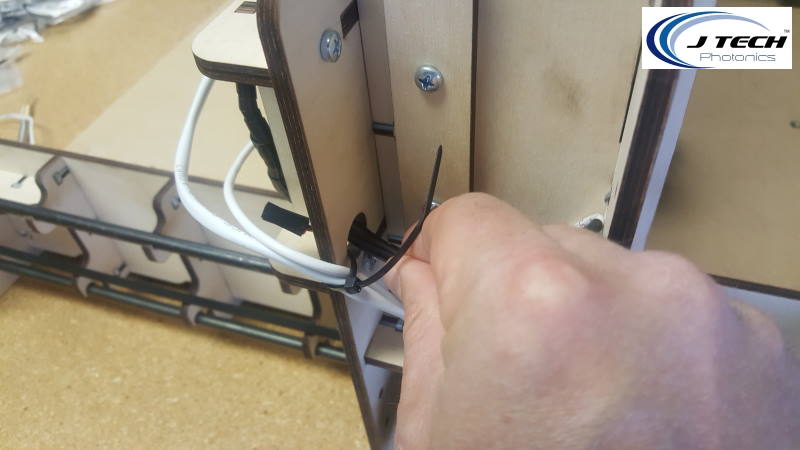
Step 5: Run the Extension Cables to the side of the machine
Next you will need to move the gantry as far from the GRBL controller as possible. Leave some slack in the extension cables to where they won’t be tension but will also not touch the waste board. Then use a zip tie to secure the cables on place to the machine.
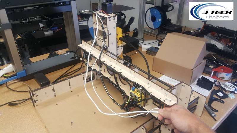
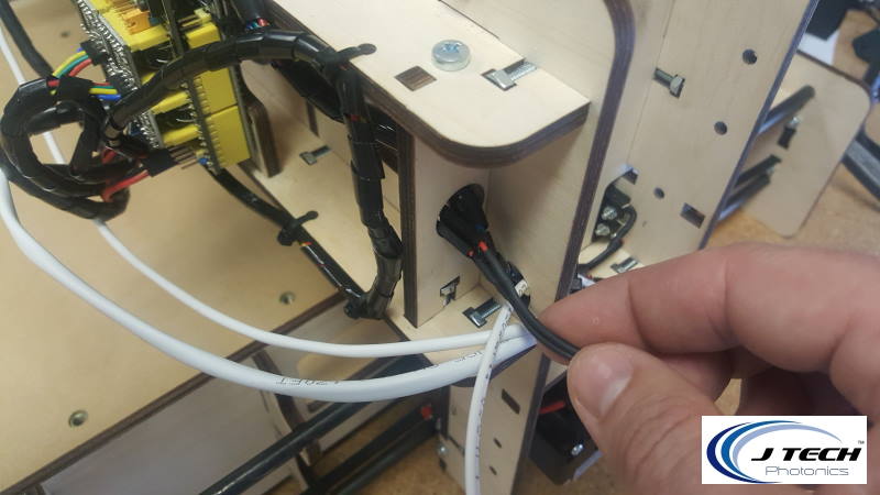
Feed the cables through the hole where the motor cable is and pull though until a small amount of slack remains.
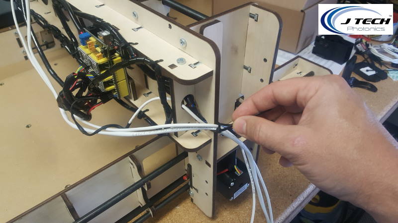
Step 6: Run the PWM cable to GRBL board
Grab the PWM and Ground cable from the bag.
Take the small two black ends and feed them up through the same hole the extension cables just went through. Then continue to follow the black wrapped motor cable until you reach the GRBL controller.
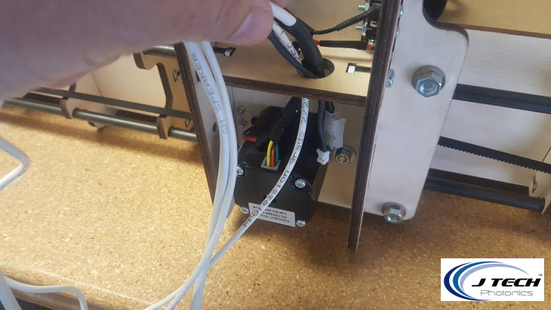
Step 7: Move The Z Limit Switch Wire
We are going to upgrade the firmware to GRBL 1.1F, so the switches have moved in this version. Move the Limit switch from Z+ to the D12 pin. It is on the top of the board.
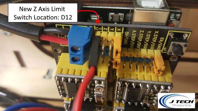
Also, make sure you have the two jumpers in at the X location.

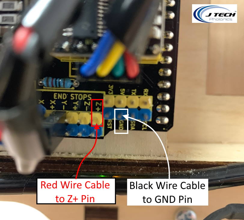
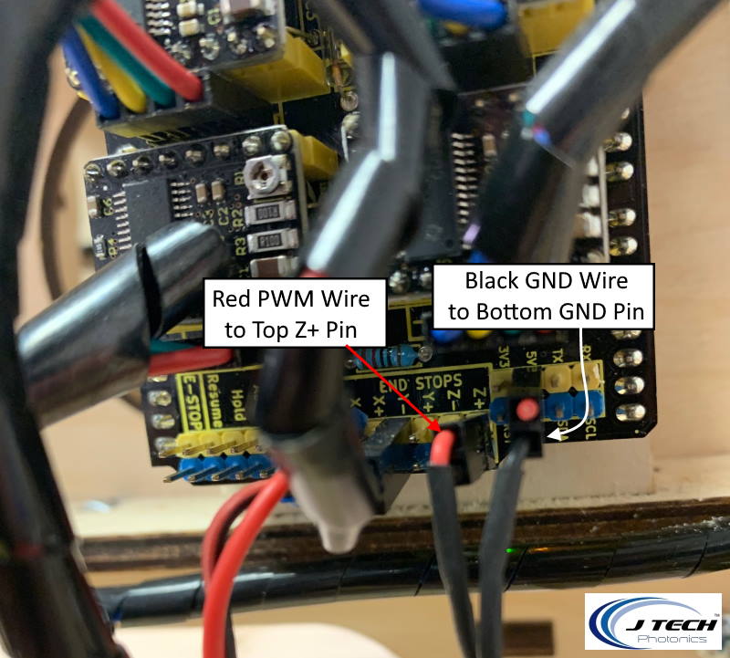
Step 8: Connect the PWM wire we just fed into the machine.
The wire we had the two black connectors on and fed to the GRBL board now needs to be connected. Take the Black wire header and put it on the black GND pin. Take the Red wire header and put it on the Z+ pin.

Step 9: Connect the PWM cable to the Laser Driver
Put the driver next to the machine in a safe place. There are sticky pads if you want to permanently attach the laser next to the machine on a board. Then take the thinner PWM cable you just connected to the GRBL board and put it into Terminal H4 on the back of the laser driver. It should have a black dot on the connector and the cable should have a black Molex connector.
Step 10: Connect Laser Cable to Driver
Take the extension cable and put some zip ties in it to clean it up.
Then connect the thick laser extension cable to the laser driver board in terminal H3.
Step 11: Connect the Fan Extension to the Laser Driver
Take the small JST for the Fan and connect it to the fan connector on the driver board.
Step 13: Connect Laser to the Extension Cables
You might need to zip tie the laser cables to clean them up.
Then connect them to the extension cables on the top of the gantry.
KL744 Electrical Hookup
If you have the large KL744 machine, your controller will look a bit different. You will have screw terminal break out board that you will connect to. It is in this picture here:

After you upload the new firmware (next step), you will connect the following.
Z Limit moves from D11 to D12.
Laser Input Red wire + signal in D11 screw terminal
Laser Input Black wire – signal in GND screw terminal

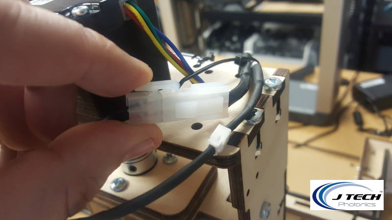
The cable from the interface board is the small one with the black connector on one side. It hooks into terminal H4 on the back and screws into the D11/GND on the other side. The input cable from the laser controller is circled in the picture in terminal H4.

Software Setup
In this section, we will upgrade your firmware on your machine to be able to engrave pictures and use the laser as part of your CNC machine.
Step 14: Update your GRBL firmware to 1.1f
Download GRBL 1.1F Firmware
- Download and extract: 1.1f ( Main Branch Merge – NEW)
If you want to check and see if there is an even newer version, then go to the main GRBL page here in the release section.
Now that you have your firmware downloaded and have extracted the .hex file, we will walk through the rest of the process.
Load Your Firmware
For MAC: Download Hex Uploader
For PC: X loader is a cool program that makes it easy to load new firmware to your controller. You can download it here:
After you download the file, extract it and run the application. You should see a dialog box like the following:

Browse for the GRBL “.hex” file. Choose “Uno (ATmega328) in the Device drop down. Select your COM port and put the Baud Rate at 115200.
Can’t figure out your COM port for your machine? Here are some videos to help:
Finding COM Ports in Windows 10
Finding COM Ports in Windows 7
Press the “Upload” button. It should say “uploading” for no more than a minute and then it will say “completed” and the size of the file uploaded. If it runs forever, you have either the wrong device chosen, the wrong COM port, or the wrong Baud Rate.
You now have the new version of firmware on your machine.
Step 15: Download Lightburn
We recommend using Lightburn software to run your laser on your BOB’s machine. You can download the trial here:
https://lightburnsoftware.com/pages/trial-version-try-before-you-buy
You can purchase a licence for it here:
https://jtechphotonics.com/?product=lightburn-software
Once you download the software, install it on your computer you are using to connect to the BOB’s machine.
Configuring Lightburn
Ok, now that you have downloaded Lightburn software, we can get started with the rest of the setup. When you install the Lightburn software, you might see Windows trying to protect you. Click on the bottom “Run Anyway” button to install it. The Bob’s CNC has some things you need to change to get it all working, so we will cover it here.
When you first run Lightburn, you should have a quick setup wizard walk you through the setup. Here is what you need to do to get it set up.
Step 16: Create your device in Lightburn
If you have your COM port selected and connected in lightburn, then you might be able to use the “Find My Laser” feature in the Device Setup. We are going to show you how to use the “create manually” because it always works and you get the correct settings.

Choose GRBL from the list:

You need to have GRBL 1.1f installed on your machine to do pictures. If you followed the instructions from the previous step where you put your firmware on then you are good.
Choose Serial/USB:

Name your machine and put in the dimensions.
The dimensions will set your grid size in lightburn. This is the dimensions for the E3. The E4 will be larger.

Choose your origin and keep “Auto Home” green

Click on “Finish” to complete setup

Step 17: Finish Setup
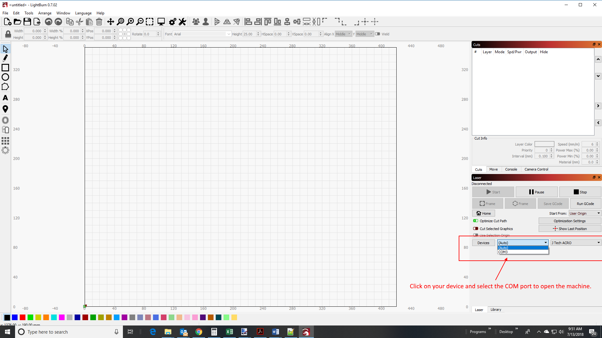
Click on the bottom right to select your machine from the drop down and click on the COM port to connect it. Make sure the USB cable is attached and the power to the machine is on (plugged in).
Check your GRBL Firmware Version
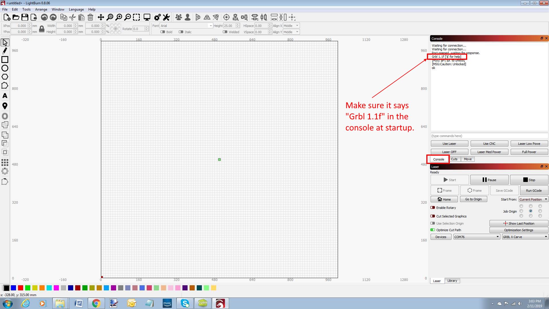
Lightburn works best with the newest version 1.1f with dynamic laser mode enabled. When lightburn connects to your machine, you will see in the console your version you are on. If it does not say “Grbl 1.1f” then you have the wrong version.
Home the machine
You need to Home your machine before you do anything else. The machine will be locked until you home it. Make sure your wires are not interfering with your switches or access to your switches by your machine.
Choose your Speed and Job Origin Settings
We normally use inch/min for our speed. Other people use mm/min. I would say at least to use one of these as this is what people normally will be used to when on the forums or for help with us. ****This step is important! If you have the speed set to mm/sec or inch/sec then it will be 60 times too fast!****

Click on the Console window to look at your setting.
Type in “$$” to see your settings. You might need to scroll down on the right to see them. Check the $30, $31, and $32 values.
Change them to be:
$30 = 255
$31 = 0
$32 = 1
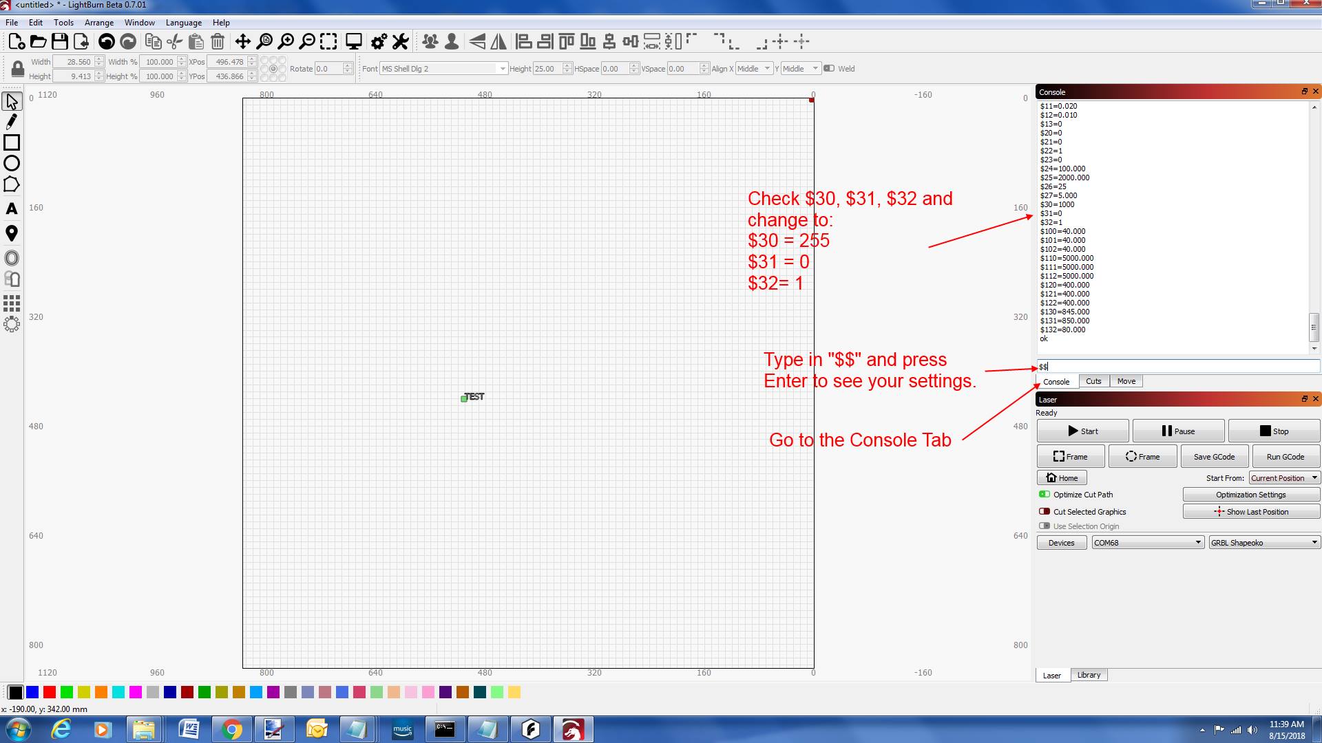
To change the value, type it in the the same place you typed in the “$$” command. Just type in “$30 = 255” and press enter to change the value.
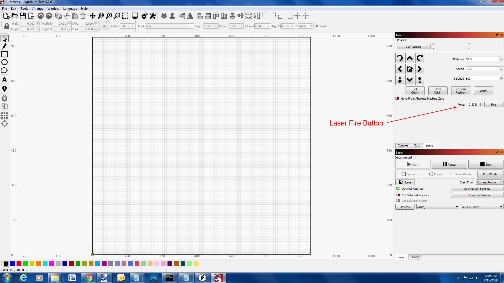
Set up you device settings to Enable Laser Fire Button and set your S Value to 255.
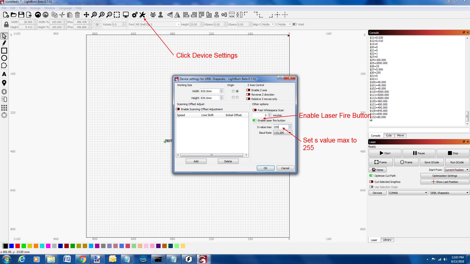
Restart the software to see the laser fire button.
This button is good for looking at your position to find where you are in low power and to use for focusing. **You might need to go up to 5% or higher to have this work for your laser.
Home the machine again… You just restarted.
Jog the machine to make sure your directions are correct.
The BOBs machine will home to the back left corner (looking from the front). This will be your 0,0 on your machine. You will have to then look at the grid and realize everything will then need to be rotated -90 degrees. Try to jog the machine in Y+ and X+ and make sure it works.
Make sure you are not in “Beginner Mode”:

Step 18: Do the Hello World Example
Now that you have lightburn set up, lets start by doing an engraving. Let’s go into lightburn and write some text. We wrote “Hello World”.
Because the BOBs machine has the 0,0 in the bottom corner of this grid, you will have to rotate the text to have it engrave correctly.
There are a few modes of engraving:
- Line (this will be an outline)
- Fill (this will fill in the text)
- Fill + Line (this will fill in the text and then outline the text)
Let’s choose Fill + Line
Double click to get to the settings for speed and power.
Jog the machine to your desired location on the board. We put down a piece of birch plywood to try out. Set the “start from” to “current position”. This will start the laser from wherever you will jog to. Choose your origin. This is where your laser will engrave from. We chose center in this example. Your green dot will be where the laser starts from to engrave.
Make sure your laser driver is on. If you can’t get it to turn on, press the small red reset button for the power interlock.

Set your position using the jog buttons and then you can look by using the laser fire button to see where on the table you are.
Frame the engraving and then press start to begin. Frame will move the machine without the laser on to show the boundary of the engraving to make sure you have it in the correct place.
The machine will start and the engraving will happen.
Your engraving will be on your machine correctly because you rotated it.
There it is! You have finished setting up your BOB’s CNC laser upgrade from J Tech Photonics!
Purchase the Bobs CNC Laser Upgrade
Disclaimer
The laser used in this project is very powerful and all safety precautions must be taken. Use proper safety eyewear to prevent injury to eyes. This is a project and J Tech Photonics, Inc. is not responsible or liable for any and all damage or injury caused to people or property. The use of these instructions to make a laser cutter is under your own discretion and all safety precautions should be followed. J Tech Photonics, Inc. is not affiliated in any way with BobsCNC and they may change hardware and software at any time making these instructions invalid.