

![]()
RAMPS1.4 Laser Upgrade
The RepRap project has quite a bit of different electronics. Many of the popular machines use a variation of just a few boards. Here are the details for upgrading the RAMPS1.4 controller to output laser control.
The details of the RAMPS controller can be found at:
http://reprap.org/wiki/RAMPS_1.4
Hooking the Laser Up
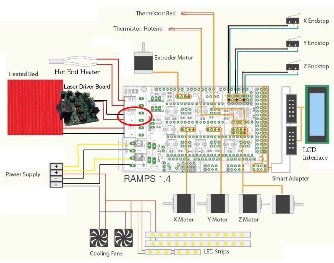
So it is pretty easy to do this upgrade because the terminal that is used already has nice screw terminals to connect wires. We are going to use the output associated with the extra FAN output to control the laser. This is terminal D9. Simply connect the “+” wire from terminal D9 to the “+” input of H2 on the laser driver board. Then, connect the “-” wire from terminal D9 to the “-” input of H2 on the laser driver board. You are all ready to go!
If you are using the Molex Mini Fit Jr. Cable, then connect to the input laser driver connector H4. Connect the red wire to the positive terminal D9 on the Ramps1.4 board and the black wire to the negative terminal on the Ramps1.4 board.
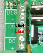
Picture showing the terminal D9 connection.
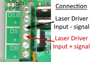
Close up of terminal D9
Software
The software is the same for all of the upgrades here. The commands to turn on and off the laser are:
LASER ON: M106
LASER OFF: M107
Using PWM to control the laser
You can have power control as well with the RAMPS1.4 board. Simply use “M106 Sxxx” command to turn on the laser where “xxx” is a number between 0 and 255. 255 is full power and 0 is off.
- M106 S255 = Turns the laser on at full power
- M106 S0 = Turns the laser off
- M106 S127 = Turns the laser on at 50% power
- M107 = Turns the laser off as well
Marlin Firmware for Lightburn
Lightburn software works with the Marlin firmware that you are most likely using on your 3D printer with your laser. You can download the trial software here to make sure:

Click Here to Buy your laser upgrade kit now!

Remember Safety First!

We sell laser shielding to block laser radiation and reflections!
Does it will work with 24-volts powered RAMPS_1.4?
I look at the above implementation and the following comes to my mind:
If I outfit my RAPMS 1.4 printer with laser the Extruder motor and the extruder hotend can be removed. That leaves the thermistor for the hot-end open for other use, why not use that on the laser to measure the casing temperature and control a FAN to keep the laser properly cooled? I usually do not do any coding, but this seems simple enough to implement. Something like this already exists when printing with PLA the top side of the hot end has to ne cooled with a fan. The fan control comes from the RAMPS and it is a function of the hot end temperature.
Also since we do not need a hot-bed for the laser, that can be disconnected as well together with the hot-bed thermistor and used for alternate laser control as well.
That is a cool idea. There needs to be some modification in the firmware to implement this, but shouldn’t be too difficult. Most of the Marlin and other firmware checks to see a minimum temperature and then there is a profile for keeping the cooling correct.
We mostly use the fan control for the laser because it has PWM functions in most of the printer firmware out there already installed. I think it would be cool to control the laser still with one of the fan outputs and then use the thermistor to control/monitor the laser cooling. I think the fan would be on most of the time because you want your laser to be as cool as possible, but it would still be neat to monitor the laser temp all the time!
You just shipped my order out today, after arrives I am willing to work with you on testing these things. I have a 3D printer which I can dedicate to this. It is a ramps 1.4 with a large LCD screen and SD card reader as well, so I don’t need to be connected to the computer all the time to run a program on it. I am not too much of a coder myself, but I can probably change some basic parameters on the Ramps config before uploading. Also right now I am running 2 fans, one for the electronics box and the second which is cooling the print head while the printer is working. The duty cycle on this can be adjusted from a knob – or from the reperier host.
Appreciate you sharing, great post.Thanks Again. Really Cool.
My D9 on the ramps 1.4 gives an output from 0 upto 12 volt with the M106 S0..255) command.
Is this the proper voltage (max 12V) to put on the H2 connector at the driver board to get 100% laser power? Or does it has to be from 0 upto 5 Volt?
I dont know what the specs are for the H2 port on the driver.
Wanted to know for sure before i order the board. A laser 2 Watts is on it way here but the driver that comes with it is TTL only to switch on or off (5 volt).
Thanks in advance.
The H2 and H4 input to the laser driver support voltages between 3.3V and 36V. 12V from the RAMPS 1.4 will be fine to use and will turn the laser on. If you want power control, then use the PWM function. Most firmware for the RAMPS board have this built in with the M106 command. M106 S255 will be full power on.
I am using 24v for my system so what comes out of D9 is 0-24v will it still work or do I need to use black wire to D9 and red wire to a 5A 12V buck converter? I have done that with a 12v fan I was using so I know it works but would love to use the full 24v.
Btw, which is better 255 steps of 24V or 255 steps of 12v for the final output?
I am curious, I have 12v required for my laser driver, and a 0-5v TTL signal required. Is this what I hook to D9? Doesnt that have a potential output of 12V?
I was told that if I exceed 5V, I would fry the driver. am I not seeing this properly?
Is the fan output only 5V?
Please explain this
The laser driver requires 12V for the power input. We provide the wall power adapter for this.
For the laser driver input signal, it can be 3.3V to 36V. Hook up the laser driver input to the RAMPS 1.4 D9 connection. You can have 12v on this signal and the laser driver will be fine. Terminals H4 and H2 are isolated inputs.
Yes, the fan output is only a constant 5V. It is on when the laser driver is turned on and enabled.
how can the TTL signal be higher than 5V?
I am unsure of what you’re saying here.
I was under the impression that 5V was max, and 0V was off. Am I missing something here?
I read that 5V was absolute max for TTL. do I need some sort of voltage divider to bring the 12V down to a max 5V? or does PWM change things here?
Can you please explain in a little more detail, or direct me to somewhere with more detail, I don’t want to fry my driver.
or are you telling me that the TTL Signal on my driver is really just the GATE of a MOSFET?
Need more info before I hook this up, as I am sure if I fry something, you are not going to buy me a new driver, am i right?
Hi Michael,
Yes, you are correct that TTL is supposed to mean just 5 Volts. We use that term on the board even though the input can accept higher voltages. The input is protected by a digital isolator that can handle more than 5V (up to 36v). You can hook up 12V to it and it will be fine. PWM does not change anything. You can modulate the frequency of the signal up to 5KHz with no problems. If somehow something happens that you fry your driver by putting 12v on the input we will replace it under warranty. This has never happened before, so I don’t think you will have an issue. I appreciate the concern you have though to make sure you are properly setting up the laser! 🙂
Best Regards,
Jay
Hi,
I want to implement this solution on the GT2560. I see it has PWM fan output but it has a 3 pin socket and my laser driver has only 2 input pins. Am I supposed to connect black-black red-red and ignore yellow output from the board? Or there is a more complex circuit I need to create?
thanks
works on my prusa i3? helpme please
Hey Guys,
I see how you can do this but what g-code sender are you using? I use repetier host but it only works with my printer head set up. Is there another marlin compatible g-code sender out there?
Im Guessing the laser driver board is a ttl board ?
using monoprice maker select v2 with elsamaker laser, ramps 1.4/mega 2560 and marlin firmware. Somehow I am having to set fan to full speed to turn laser off and bring the speed down to set power. In bed at the moment, but was hoping someone might have some input without me going to the office and detailing every little thing…
Thanks
ben
I have a Ramps 1.4 Plus 2, this card comes with an Input called Laser, can I use this port? can I keep my 3d printer capabilites to print when I need and grab or cut when required?
Hi my problem M106 S0 =laser on M106 S255=off what’s wrong what is problem
M107 S0=off M107 S255=off
the laser in me is three wired one red one black and yellow