

We now have the new Safety Interface Board for control lasers with integrated drivers – 24W, 44W, and 64W.
The J Tech Photonics High Power Laser Diode driver is designed with features, protection, size, and cost in mind.
Two Versions – 5amp and 2.5amp
and… New Safety Interface Board!
Added Safety for Driving Class 4 Laser Diodes
This go around we have kept all of the features that make this laser kit awesome – precision laser trimmed regulators for constant current to the laser, 0.01 tuning resolution, digital isolation, soft start, esd protection, current limiting, and the list goes on. But NOW we have more safety in mind as well! The US Federal Government has a list of things that are required for operating these high power class 4 lasers. They might seem trivial, but they could save your eyesight! Here is a run down of the new safety features to protect yourself and others:
- Key Switch – This key is needed to enable the laser. When the key switch is turned on, the laser is enabled and the key CANNOT come out. You can only remove the key when it is disabled. This feature is good if you have curious children or have your laser in a shared area and want to limit use. Just take the key out and hide it!
- Remote Interlocks – This feature allows for addition of switches to your enclosure so when it is open, the laser will automatically turn off. Also provides for the addition of an E Stop button for the laser, which is always good for if you need to stop the laser super quick! Add as many switches as you want to make a super safe area for your laser machine so nobody can accidentally look into the laser.
- Power Fault Protection – This one may seem like it is not needed, but hear us out. Consider your power goes out in your area where the laser is located. You were running your program and then everything is dark… Power doesn’t come back on for awhile… long enough for you to forget that the laser was left ON! You come back and are checking your laser and boom, the power is back on, right when you are looking straight at it. Well, don’t worry because the laser will be disabled whenever the power to the driver is lost. Press the reset button and you are back in action!
- Emission Indicator – The small little LED on the front to let you know your really super bright laser is on… They require this in case you are using an infrared invisible laser.
Designed for Easy Integration with Digital Isolation
The high power laser diode driver is cost effective and easily integrated into industrial, research, or enthusiast projects and products. The driver can be operated in CW mode or in Input Control Mode to be interfaced to remote electronics. This new design uses digital isolators for super fast response and input range while protecting the laser from deadly ground loops. The board has screw terminal connections as well as molex mini-fit Jr. connectors for easy connections to external equipment for control and the laser diode output.
Current Limits and 0.001 Adjustable Current Resolution
This laser diode driver will provide up to 5 amps or 2.5 amps of constant regulated and protected current to the diode. Configurable current limits with jumpers and adjustable output with an analog trim pot. It also can be remotely controlled with an digital isolated input with a super huge range of acceptable voltages for turning your driver on and off. Does your equipment in your project or system that you want to interface with have backwards logic? No problem! There is a jumper for choosing inverted or non inverted logic as well! Perfect for integrating into any final product or project.
Simple, effective, and inexpensive current source for all of your laser needs…
Features:
- High power current source for driving Laser Diodes and Light Emitting Diodes.
- Current Range of 5 amps or 2.5amps
- Current Ranges are adjustable in 1amp or 500ma increments.
- Integrated cooling fan
- Soft start for diode protection.
- Reverse diode and ESD protection.
- Thermal Protection and Over Current Protection.
- Federal Compliant Safety Features
- Key switch, Remote Interlock, Power Fault Reset
- Compact Size.
- CW Mode and Input Control Mode.
- Digitally isolated control input.
- Control from CW to 2.5 KHz.
- Configurable Input signal: Inverting /Non-Inverting.
- Multiple connector options for both Laser/LED output and control input.
- LED status lights for input laser enabled and laser on.
Safety Interface Board Specifications
| Specification | |
| Minimum Operating Voltage | 24V |
| Maximum Operating Voltage | 24V |
| Current Adjust Modes: | External PWM, Internal Potentiometer |
| Internal Power Mode Accuracy | 1% of value |
| Laser Diode Protection: | Soft Start, Reverse Voltage, Current Limit, Thermal Shutdown |
| Integrated Safety Features | Laser Enable Key Switch, Integrated Laser Interlock, Power off Reset, LED Indicators |
| AC Adapter Input Voltage: | 100 – 240 VAC |
| Control Signal Digital Isolation Voltage: | 4500 Vrms |
| Minimum Control Signal ”Turn On” Voltage: | 2.8 Volts |
| Control Signal Maximum Voltage: | 24 Volts |
| Control Signal Maximum Current: | 50 ma |
| Control Signal Maximum Frequency: | 3KHz |
| Connectors: | Screw Terminal and JST PH Connectors |
| Operating Temperature: | 0 to 40 °C |
| Storage Temperature: | -40 to 70 °C |
| Dimensions: | 4.2” x 3” |
5 amp Version Specifications
| Specification | HCDBSAFDA5AMP |
| Current Source Range: | 0 – 5 Amps |
| Current Limit Jumper Settings: | 1, 2, 3, 4, 5 Amps |
| Compliance Voltage w/12V adapter: | 8 volts |
| Current Resolution: | 0.1% |
| Current Adjustment: | Analog Trim Pot |
| Current Range Accuracy | + – 5% |
| Laser Diode Protection: | Soft Start, Reverse Voltage, Current Limit, Thermal Shutdown |
| Integrated Safety Features | Laser Enable Key Switch, Integrated Laser Interlock, Power off Reset, LED Indicators |
| AC Adapter Input Voltage: | 100 – 240 VAC |
| Control Signal Optical Isolation Current Required | 3ma |
| Minimum Control Signal ”Turn On” Voltage: | 2.8 Volts |
| Control Signal Maximum Voltage: | 24 Volts |
| Control Signal Maximum Current: | 50 ma |
| Control Signal Maximum Frequency: | 2.5 KHz |
| Connectors: | Screw Terminal and Molex Mini-Fit Jr™ Connectors |
| Operating Temperature: | 0 to 40 °C |
| Storage Temperature: | -40 to 70 °C |
| Dimensions: | 2.6″ x 4″ |
2.5 Amp Version Specifications
| Specification | HCDBSAFDA2_5AMP |
| Current Source Range: | 0 – 2.5 Amps |
| Current Limit Jumper Settings: | 0.5, 1.0, 1.5, 2.0, 2.5 Amps |
| Compliance Voltage w/12V adapter: | 8 volts |
| Current Resolution: | 0.1% |
| Current Adjustment: | Analog Trim Pot |
| Current Range Accuracy | Always greater than limit, no more than 15% |
| Laser Diode Protection: | Soft Start, Reverse Voltage, Current Limit, Thermal Shutdown |
| Integrated Safety Features | Laser Enable Key Switch, Integrated Laser Interlock, Power off Reset, LED Indicators |
| AC Adapter Input Voltage: | 100 – 240 VAC |
| Control Signal Digital Isolation Voltage: | 4500 Vrms |
| Minimum Control Signal ”Turn On” Voltage: | 2.8 Volts |
| Control Signal Maximum Voltage: | 24 Volts |
| Control Signal Maximum Current: | 50 ma |
| Control Signal Maximum Frequency: | 5KHz |
| Connectors: | Screw Terminal and Molex Mini-Fit Jr™ Connectors |
| Operating Temperature: | 0 to 40 °C |
| Storage Temperature: | -40 to 70 °C |
| Dimensions: | 3.6″ x 2.2″ |
Front of all Boards

The front contains:
- Power / Enable Switch
- Key Switch
- Safety Interlock (shown defeated)
- Reset Switch
- Mode Selector Switch: Left = CW Mode, Right = Input Control Mode
- LED Indicators: Left = Driver Board Enabled, Right = Laser ON
Back of 2.5 and 5amp Driver Boards
The back contains:
- Laser / LED Output Connector: Top = Negative Output, Bottom = Positive Output
- Laser / LED Output Screw Terminal: Left = Negative Output, Right = Positive Output
- Input Control Connector: Top = Negative Input, Bottom = Positive Input
- Input Control Screw Terminal: Left = Negative Input, Right = Positive Input
- Potentiometer for Analog Current Level
- AC Power Adapter Plug
- Connector for 5V fan for laser
- Remote Reset Button Connector
Back of Safety Interface Board

Side View of Safety Interface Board

Side View 5 amp Version

Side View 2.5 amp Version
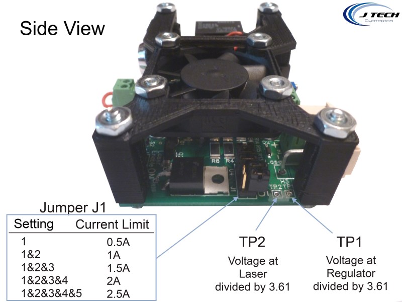
- TP1 and TP2: Allows for connection to a micro controller to update current reading on the fly. Check out the instructions here.
- Current Limit Selector: This will limit the output current of the driver to the selected level.
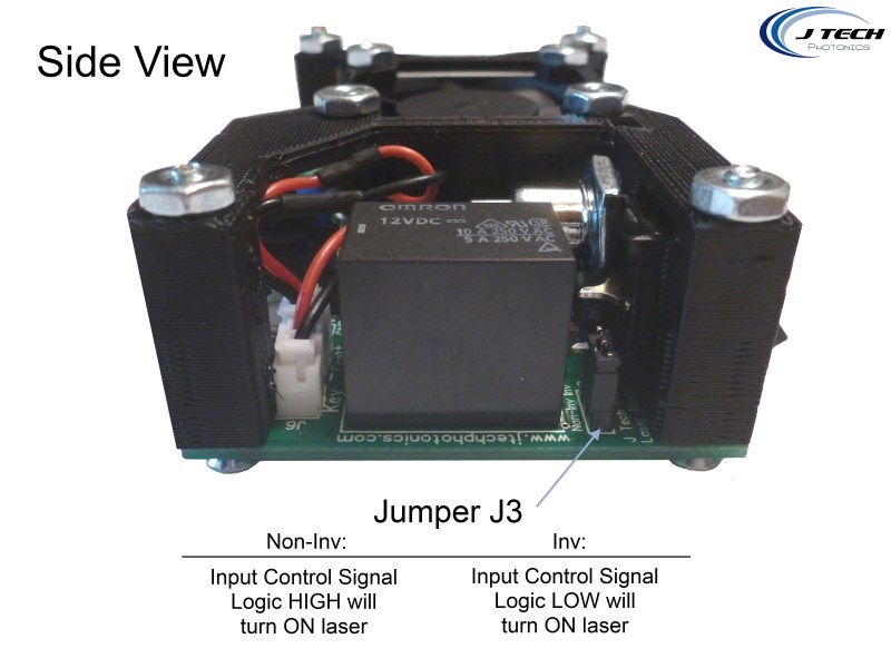
Control Signal Jumper: This will either invert or not invert the incoming control signal. When interfacing with equipment that is not under the users control, it is sometimes needed to invert the incoming logic. Left Two Jumpers On = Non-Inverting Input, Right Two Jumpers On = Inverting Input
Control Signal and Performance
The input connection provides an optically isolated input for control of the laser diode. The connection and the jumper settings were described in the previous sections. The voltage required to turn on the opto-isolator is 2.8 volts. The input can handle up to 24 volts at no more than 50 ma. The input can be cycled with no degradation up to 4KHz.
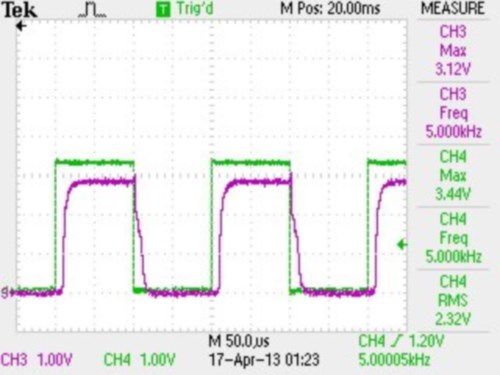
Typical Control Signal with “non inverting” set running at 5KHz. Ch 4 control, Ch 3 output.
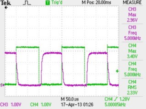
Typical Control Signal with “inverting” set running at 5KHz. Ch 4 control, Ch 3 output.
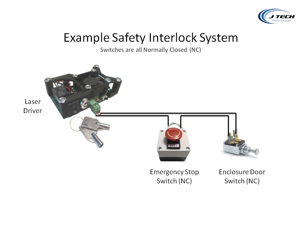
Safety Interlock
The laser driver has an interlock system which is NORMALLY CLOSED and contains a voltage in the cable of 12V supplied by the laser driver board. This means if any switch along the interlock chain becomes OPEN, then the circuit will open and the laser will disengage the laser.
Examples of use of the interlock system include the emergency stop button switch and an enclosure door switch. When integrating the laser driver and laser into an OEM machine, all entrances to the machine (enclosure doors) must have an interlock switch in order to be considered compliant with Class 4 laser rules. Multiple switches can be added along the chain when integrating the laser driver into OEM machines as long as they are wired in series.
Here is an example of an interlock system:
Accessories
Remote Reset Switch – In case your driver board is in a hard to reach area.

Add an Emergency Stop Switch to your interlock circuit. Click Here
I was wondering what kind of connector we could use for the laser fan and input power
The laser fan uses the JST type connector. You can buy it here: https://jtechphotonics.com/?product=jst-jumper-2-wire-connector
Or you can get them at a local computer store. Input power is a bullet style 2.1mm positive center. You can get the OEM connector here: https://jtechphotonics.com/?product=oem-power-connector-with-cable-6-18awg-straight
I already have laser module with constant current driver, like this: http://i68.tinypic.com/24vuwyv.jpg
It goes with 12V 2.5A power supply. Can I use this laser module with your board in order to connect it to MendelMax (RAMPS 1.4)?
I think that I need some modifications, but I have no schematics what I need to do…
Just remove the small board and use the jtech board instead.