

MicroController for Laser Current Monitoring
Many people have been asking how they might monitor the current on their laser driver board while it is running on their machines. Many people want to hook up an Arduino board to it and put an LCD to constantly watch the laser current so it is easy to adjust and to get a sense of the optical power on the work surface. Well, the good news is: We thought of that!
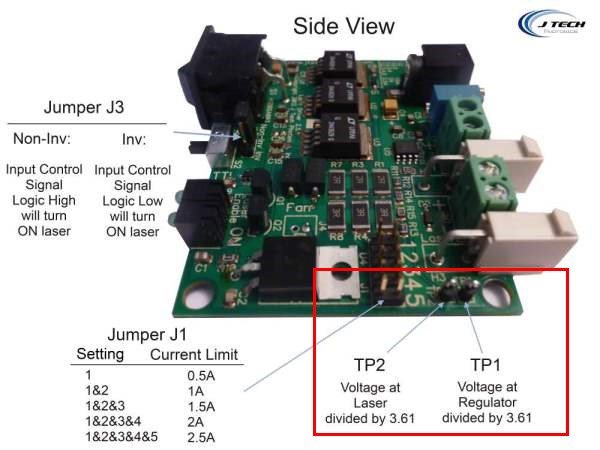
In designing the original laser driver, there are current sense resistors and test points on the board specifically to get the voltage over the current resistors from both the regulator side as well as the laser side. Looking at this voltage will give an “on the fly” level of what is happening on the board at all times. The laser driver board runs at 12V, but the connections to these test points are voltage divided to be able to work with 3.3V micro-controllers (it can also work with 5V ones by changing the level in firmware).
Connections:
On the laser driver board there are two test points, TP1 and TP2. These test points provide measurement connections for the voltage at the regulators (one side of the current resistors) and at the laser output (the other side of the current resistors). They are shown in the following picture:
First you need to connect some wires:
- Connect TP1 to analog input #1 in the micro
- Connect TP2 to analog input #2 in the micro
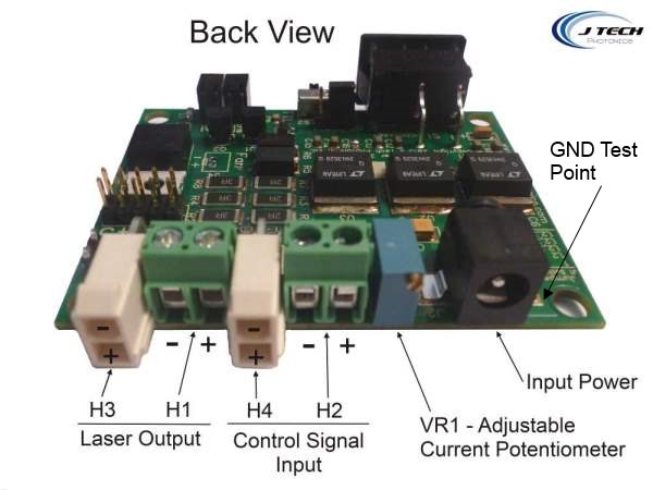
- Also, you might need to connect the GND on the laser driver to the GND on the micro-controller, but possibly not. You can also connect the GND to the AREF pin and set the analogreference to “external” to get a clean signal from the laser board without causing a ground loop. The ground test point is located just right of the power input connector looking from the back of the board.
Set up your code to make the pins you selected analog inputs. Now you can read in the voltage on the pins with your micro-controller. We will get into exactly how to do this next.
Fun with Physics!
So now that we have the physical connections done, let’s get to the theory on how to get the current value from the voltage across a resistor.
From high school physics class, the equation to get current is:
I = V / R
Which is the voltage over the current resistor divided by resistance. Considering there are multiple current limit settings, it will change the amount of resistance for the equation. So, here is a table with the resistances for the different jumper settings:
| Current Limit | Jumper Setting | R Value |
| 0.5 | 1 | 5.5 |
| 1 | 1&2 | 2.75 |
| 1.5 | 1&2&3 | 1.83 |
| 2 | 1&2&3&4 | 1.38 |
| 2.5 | 1&2&3&4&5 | 1.1 |
So now the equation is:
I = (TP1 – TP2) / R Value
The board outputs voltage at the TP1 and TP2 points divided by 3.61. This was done so the board would have a MAXIMUM voltage of 3.3V to be able to fit in the range of a 3.3V microcontroller input ( 12V / 3.61 = 3.3V). We now have to take this into account in our equation:
I = ( (TP1 – TP2) * 3.61 ) / R Value
Testing the Theory
Let’s say you used a multi-meter to look at the voltage at the test points and you wanted to know the current. Let’s take an example and work through it.
Here is an example: Running the laser at 1.5amp current limit setting and current set to 1.3amps. I use a meter and read the following:
- TP1 = 2.01 V
- TP2 = 1.34 V
So, the current is:
I = ( (TP1 – TP2) * 3.61 ) / R Value
( ( 2.01 – 1.34 ) * 3.61 ) / 1.83 –> ( (0.67) *3.61 ) / 1.83 –> 2.42 / 1.83 –> 1.32 amps
Now the Firmware!
Now that we have done an example of how you would calculate this looking at a meter and doing it on paper, let’s get the micro-controller to do this on the fly.
The micro controller is a bit different in the input reading. It will take a voltage and turn it into a number between 0 and 1023. Remember, the TP1 and TP2 voltages are divided in a resistor network before the micro-controller to make sure the maximum value on the driver board will be below 3.3V (the maximum of many microcontroller inputs). The microcontroller will also read in with a A/D and give a value in the resolution of that A/D. Let’s take the example of an Arduino board which have a 8 bit resolution on the analog inputs, so it will be 1024 levels (actually 1023 levels because you start at zero).
Let’s start with some code: Let’s assume you chose oin A0 for TP1 input and A1 for TP2. So, we now have to convert to get the real voltage at the input in the micro controller:
// read the input on analog pin 0:
int TP1Value = analogRead(A0);
// Convert the analog reading (which goes from 0 – 1023) to a voltage (0 – 3.3V):
float voltage1 = TP1Value * (3.3 / 1023.0);
// read the input on analog pin 1:
int TP2Value = analogRead(A1);
// Convert the analog reading (which goes from 0 – 1023) to a voltage (0 – 3.3V):
float voltage2 = TP2Value * (3.3 / 1023.0);
So, now you need to convert back to the 12V level of the board (you can do this in the previous lines but want to just make it explicit for instruction):
// Convert the analog reading of a voltage (0 – 3.3V) to (0 – 12V):
float voltage1_12V = voltage1 * 3.61;
// Convert the analog reading of a voltage (0 – 3.3V) to (0 – 12V):
float voltage2_12V = voltage2 * 3.61;
Now all you have to do is determine the R Value and calculate I: (from the previous example we will use 1.5amp limit jumpers with R value of 1.83)
// Calculate the current based on the current limit jumper setting:
float current = ( voltage1_12V – voltage2_12V ) / 1.83 ;
If you leave your current limit setting always the same, you can hard code it, or better yet make it a variable that can change depending on the jumper setting you are using on the board.
Averaging and Glitch Removal
So now that you have some code written for calculating current from the input voltage, let’s think about hooking this up to a display (like and LCD or USB to the computer). If you want to show it on an LCD, you probably will need to average out the readings because the LCD display will only update so fast. Also, you might have some glitches in your readings if it is a noisy environment, so averaging and throwing out outliers is a good idea.
Here is a function that will return the average current reading and can be called by the LCD display function:
float GetAvgCurrent() {
float CurrentValue = 0;
float CurrentValueAvg = 0;
float TP1Value = 0;
float TP2Value = 0;
i = 0;
while ( i < 250 ) {
TP1Value = analogRead(A0);
TP2Value = analogRead(A1);
//Calculate current for jumper setting 1.5amps
CurrentValue = (( TP1Vlaue – TP2Value ) * 3.61 * ( 3.3 / 1023 ) ) / 1.83 ;
//For normal reading over 0 set it in the average
if (CurrentValue > 0){
CurrentValueAvg = (CurrentValueAvg + CurrentValue)/2;
i++;
}
//catch the glitches that say are negative and make them zero
else {
CurrentValue = 0;
CurrentValueAvg = (CurrentValueAvg + CurrentValue)/2;
i++;
}
}
return (CurrentValueAvg);
}
Conclusion
So this outlines how to set up a LCD (or Computer) “on the fly” monitoring of the current output to the laser from the laser driver board. You can then surmise the optical power on the work surface from this reading as well. For the non-G2 lens lasers, it should be about 1:1 for current to optical power. So, if you have a current of 1 amp you will have an optical power of 1w. On the G2 lasers (like the 9mm 2.8W) you will have about 1:1.22. So in this case 1.3amps will give you 1.6w of optical power at the work surface.
In any regard, it is nice to have an LCD display to constantly look and make sure the current is what you want it to be on the driver board.
Is what you have called out as “Firmware” what you flash the arduino with? For example the
” // read the input on analog pin 0:
int TP1Value = analogRead(A0);
// Convert the analog reading (which goes from 0 – 1023) to a voltage (0 – 3.3V):
float voltage1 = TP1Value * (3.3 / 1023.0);”
does this go in the “Configuration.h” area of the ardunio flash?
Thanks.