


In the new era of “personalized manufacturing” the ability to create fast prototypes and small run production is a must for companies, entrepreneurs, and hobbyists alike. In this article you will find detailed instructions on how to create a solder stencil for surface mount technology parts.
First you will need to have the output from your circuit design tool available for the paste layer. We will then need to shrink the pads and holes by about 2 mills to allow for the spot size of the laser beam on the stencil material when processing. Then the output is saved to PDF where it can be imported into the path generating software. Then, with a simple change of some G codes, the file is ready for Replicator G and laser processing.
Equipment:
- A Makerbot or other 3D printer or CNC machine with the J Tech Photonics laser upgrade kit.
- Thin plastic transparency sheet for overhead projectors.
- A couple of pieces of paper to put under the plastic.
Software:
- Pdf creator for printing pdf files: http://sourceforge.net/projects/pdfcreator/files/
- Pentalogix ViewMate Gerber viewer software for viewing gerber files.
- Inkscape (or other software) to create G Code files from pdf drawings.
- Laser engraver extension – This generates the g-code needed to control the laser. Find it here: Inkscape Laser Plugin
Instructions:
1. From your layout program generate the output file for the “paste” layer.
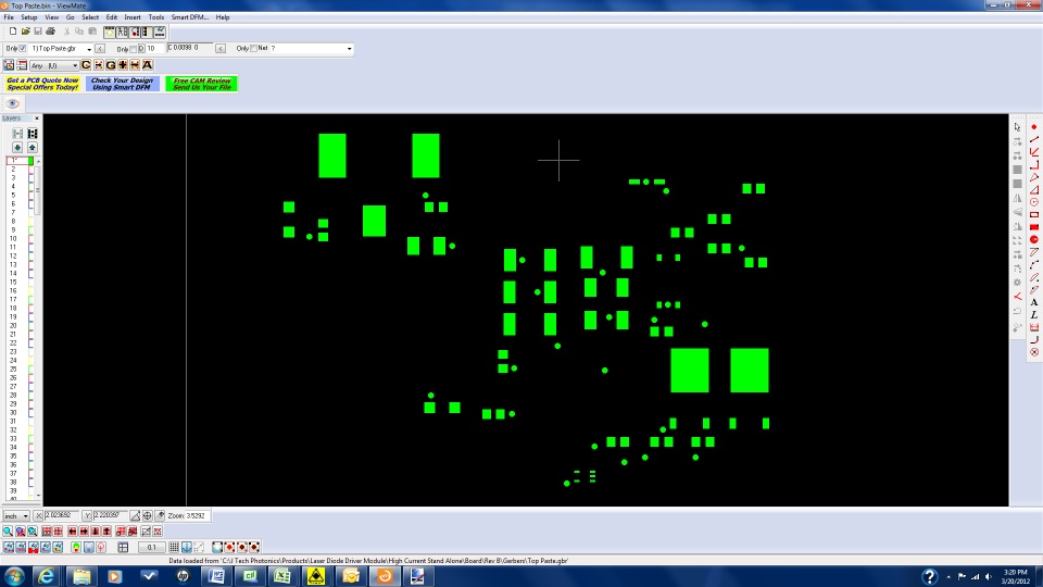
2. Open the file in a gerber viewer such as Pentalogix Viewmate. We are going to shrink the pads by a small amount (about 2 mils) because the laser spot will cut a bit bigger than the output from the gerber file.
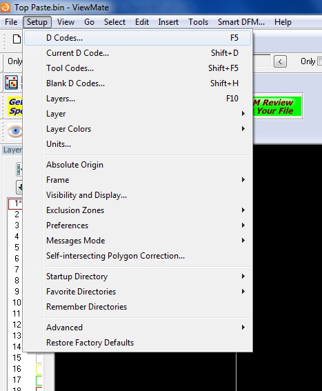
3. Choose under “setup” -> Select D Codes
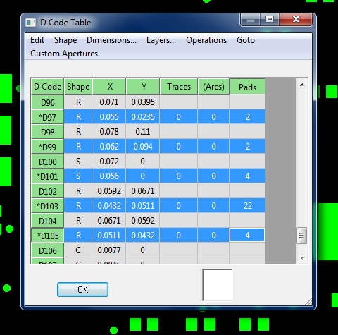
4. Using the control key, select all of the pads.
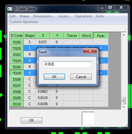
5. Choose under “Operations” -> swell…
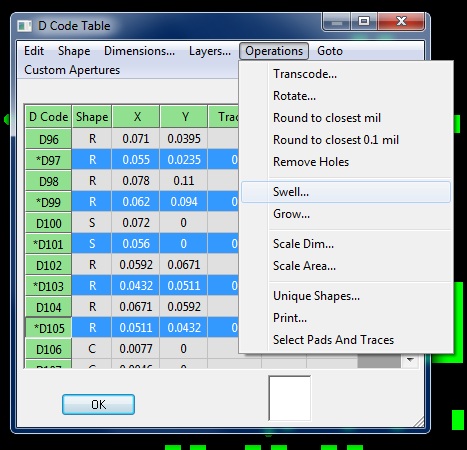
6. Type in a number to shrink the pads. A good number is usually 2 mills (-0.002).
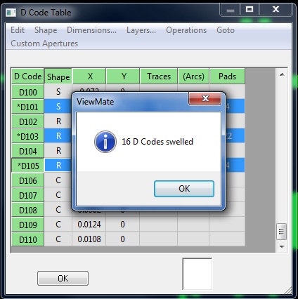
7. Press “ok” when it says how many pads have swelled and again “ok” to close the D Code table.
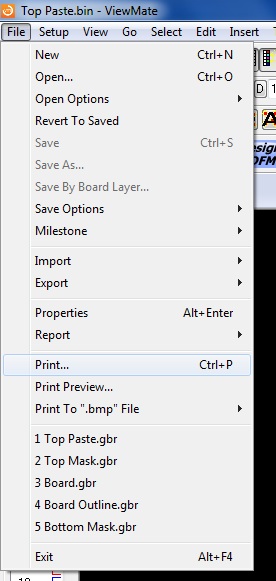
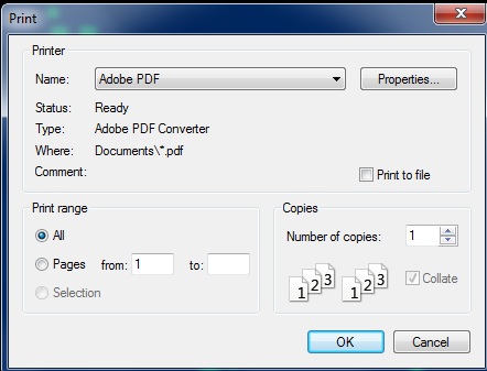
8. Now we need to export the new file with the smaller pads. Under the “File” menu choose -> “Print”. (alternatively if you do not have a pdf printer then choose “print to .bmp file”.)
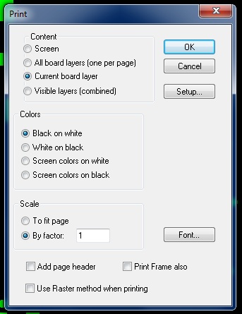
9. Make sure it is set to “Current board layer”, “black on white”, and “by factor 1”. Click “ok”.
10. Choose the pdf printer and save the new file.
11. Open inkscape and under “File” click -> “import”
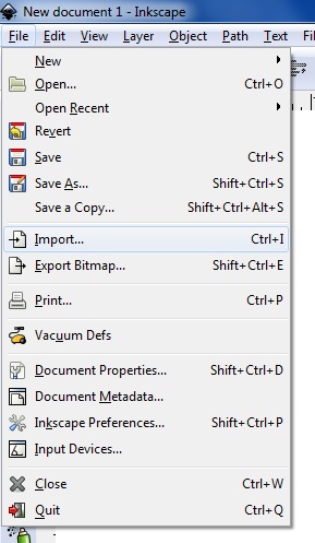
12. Choose the file and click “open”.

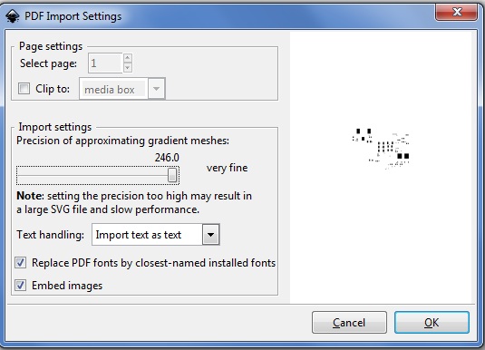
13. Choose your settings and press “ok”
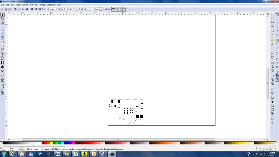
14. Select the object.
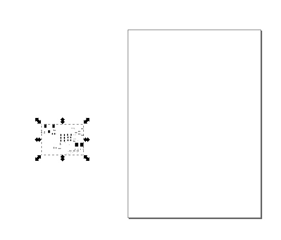
15. Move the object to the lower corner of the page. This corner will be your “0,0” reference for the Makerbot build platform.
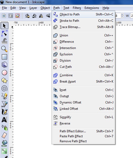
16. Click under “Path” -> “object to path”.
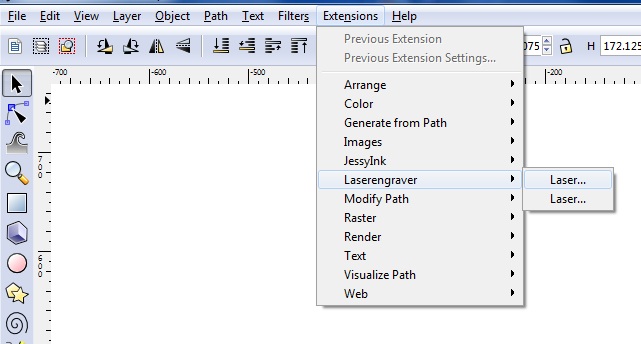
17. Click under “Extensions” -> “Laserengraver” – > “Laser”
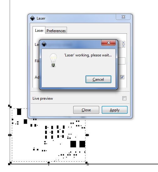
18. Choose your preferences and filename and then click “Apply”. The laser engraving speed will set the speed of the x and y motors during processing. Depending on the laser power and material/material thickness this speed may need to be adjusted.
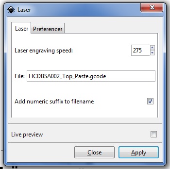
19. The G Code program will run and The g code file will be located at the location set in preferences tab of the laserengraver extension.
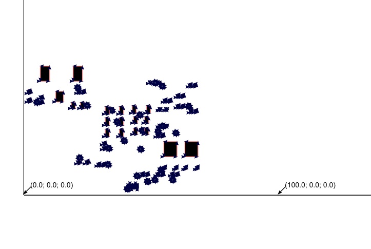
Note the 0,0 is on the left of the file and the distance of 100mm is shown on the right. Use this when setting the 0,0 location on the makerbot.
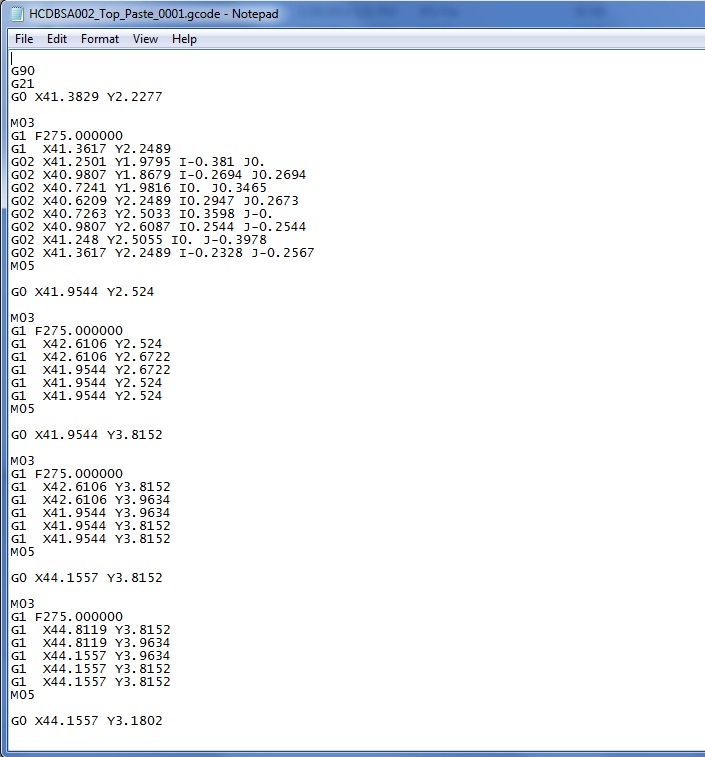
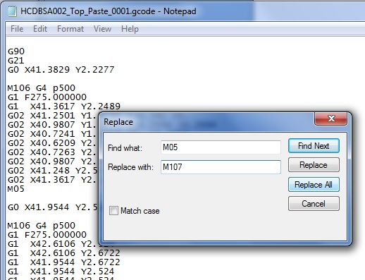
20. Now we need to adjust a command to turn the laser on and off to cut the holes in the material. Open the file in Notepad.
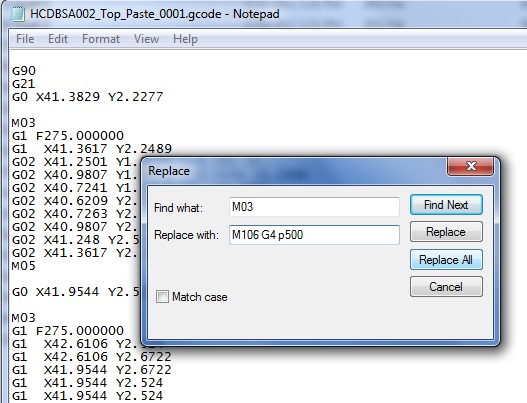
21. Under “Edit” click -> “Replace”.
22. Change the “M03” to the “M106” command. It might be useful as well to include a “G04 P500” command as well to pause for 500 ms (or some other time) before moving in order for the laser to heat up the material before the motion starts. Click “Replace All”.
23. Change the “M05” to the “M107” command to stop the laser after moving. Click “Replace all” and close.
24. Make sure to add a carriage return between the M106 command and the G4 p500 command. They need to be on separate lines for the Replicator software to interpret them. After you are done press “save” to save the file with changes.

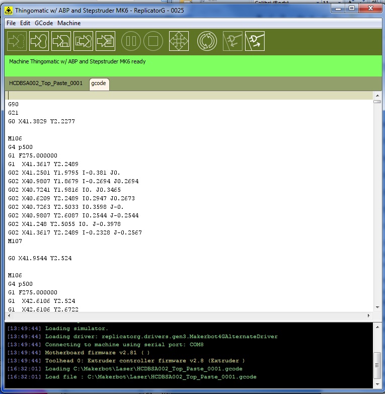
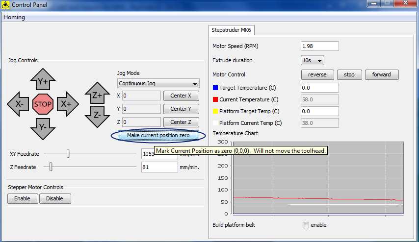
25. Open Replicator G software and open the g code file we were just working on. Under the control panel, adjust the position in x and y so that the laser is in the bottom left corner of the base (like in the inkscape picture).
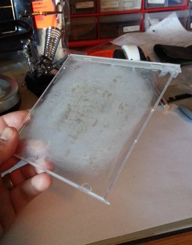
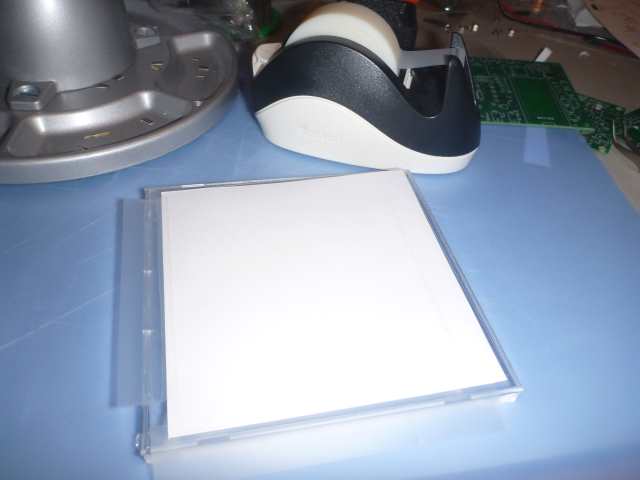
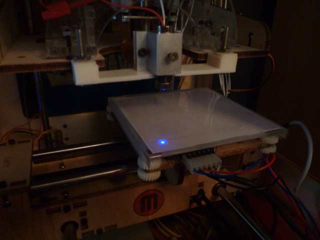
26. Prepare the material and the base for the build platform. I used an old CD case to protect the build platform and then put sheets of paper on top.
27. Cut the paper to fit on the platform. Normally, using about 3 sheets of white paper under the mylar sheet tends to allow the mylar to cut without damaging the underlying base.
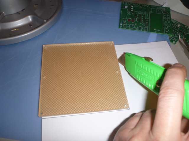
28. Cut the transparency to fit the platform.
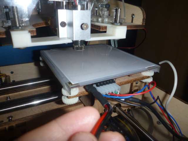
29. Tape the sheet to the paper and the base and transfer it to the makerbot.
30. Make sure the Control cable is connected to the makerbot and the driver.
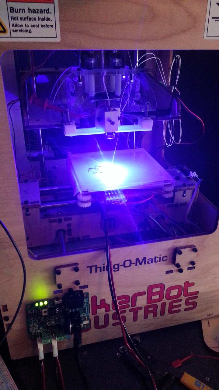
31. Using the potentiometer adjustment, set the laser driver to a level that is low enough not to cut the material but can be visible to see. A good point of reference is to turn it all of the way off then work up until some light is visible. Remember to use your laser safety goggles at all times when the laser is on.
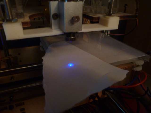
32. Fine tune the x and y settings so they are where you want them and then focus the beam in Z. First make sure the lens is adjusted enough to allow for the fine tuning with the Z control. Using a piece of paper, place it over the material and adjust the laser in Z until the smallest beam size is found on the paper.
33. After all of the settings are found, click on the “make current position zero” button. This will set the current location as zero for the processing.
34. In Replicator G, press “Build” and let her rip! The laser will then begin processing the stencil.
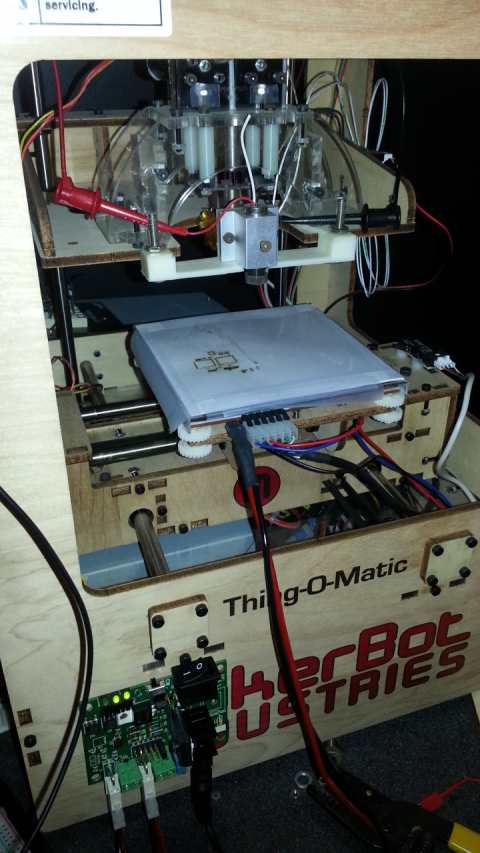
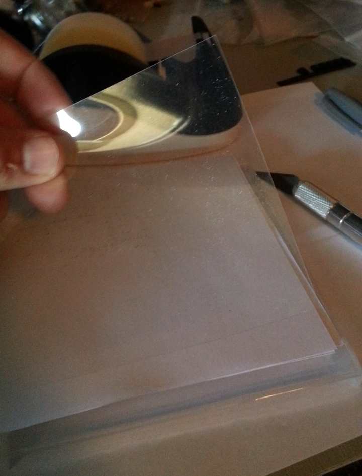
35. Remove the plastic from the paper. The paper will also be cut so remove the stray pieces from the stencil.
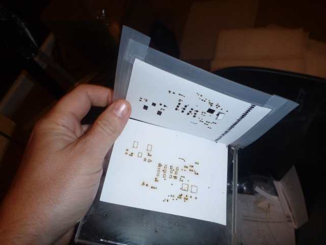
36. Clean up the rest of the stencil by pulling any pieces off or use a small hobby knife to remove hanging pieces. You now have a finished solder stencil!
Hi there,
What Power level and speed did you use to get reasonable cuts in the Sheet?
Thanks
We get excellent results using 550 mm/min at 1.5 amps on the 2.8W kit. You need to maybe use an exacto blade to remove the little “nibs” of plastic from the larger pads on the sheet, but you can get really fine detail on fine pitch parts. If you just have really big pads, then you can slow it down a bit more to get it to cut all the way through on all of the pads with no post processing needed.