

These are instructions for the All-In-One Bundle for the CNC 4 Newbie Upgrade machine located here: https://jtechphotonics.com/?product=cnc4newbies-all-in-one-laser-and-mounting-kit-bundle.
Overview
This guide walks you through mounting and wiring the J Tech Photonics All‑in‑One Laser & Mounting Kit Bundle on your CNC 4 Newbie machine.
Before you begin, please ensure you have:
- Your machine fully assembled and tested (spindle motion, homing, limit switches, gantry travel)
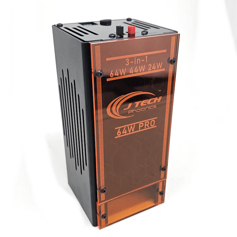
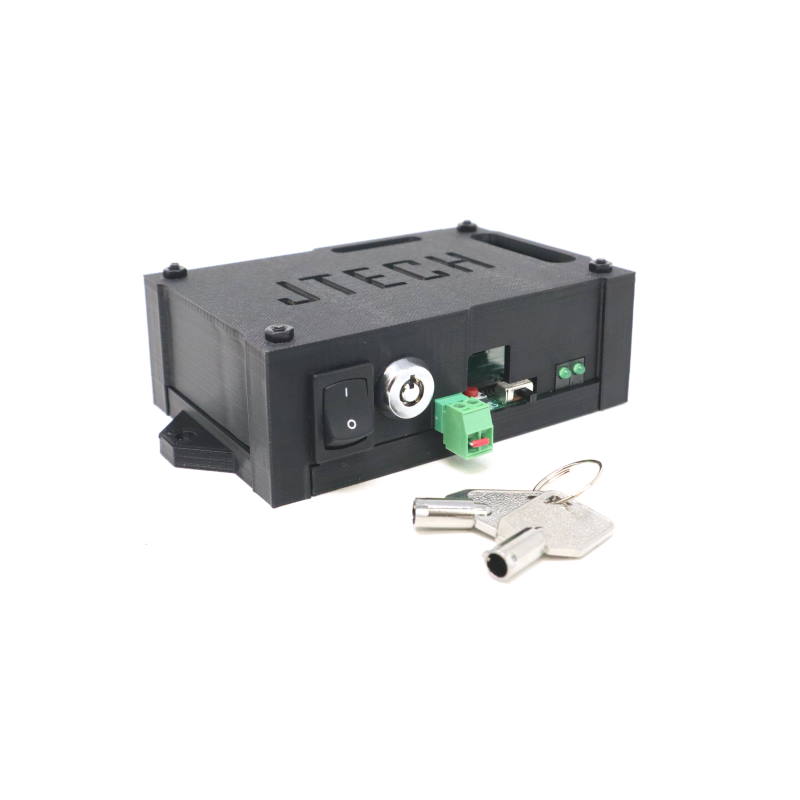
- The laser bundle kit unpacked and identified: laser head, driver/interface board, extension cables, mounting hardware, safety glasses, and mounting option you selected.
- A workspace cleared, proper ventilation, and appropriate laser safety measures in place (see Safety section below).
Step 1: Choose Your Mounting Option
The bundle supports a variety of mounting options tailored for CNC 4 Newbie machines.
Select the method you ordered or prefer:
- Front‑mount on router/spindle holder — attaches to the front of the Z‑axis spindle holder.
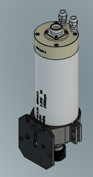
- 80 mm Spindle Clamp Mount — laser mounts beneath an 80 mm spindle shell (if your machine uses that style).
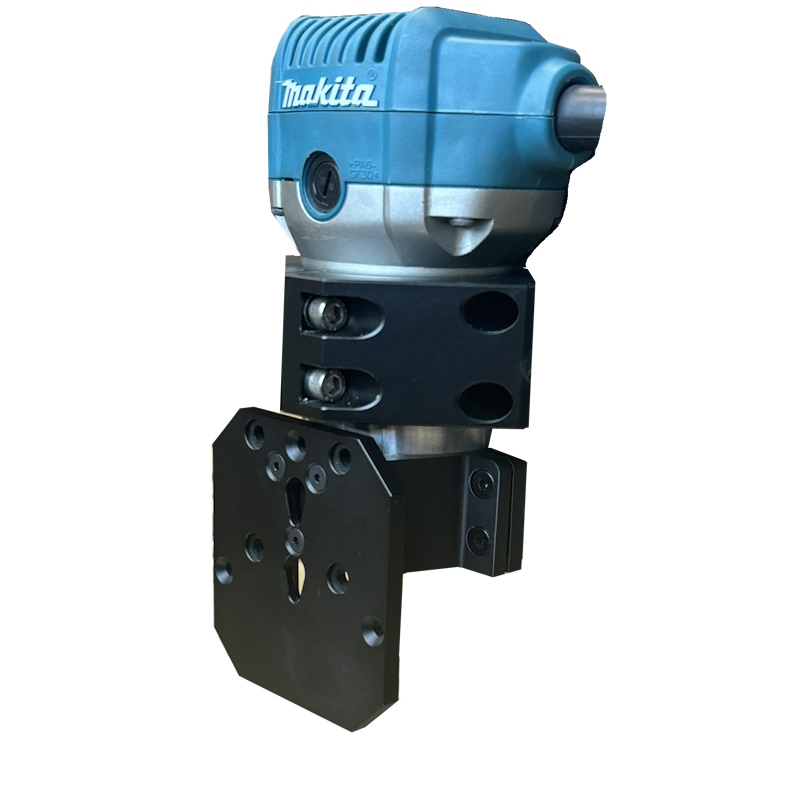
- Router Clamp Mount (DeWalt / Makita style) — laser mounts to the bottom of your router unit if you plan to switch between routing and laser.
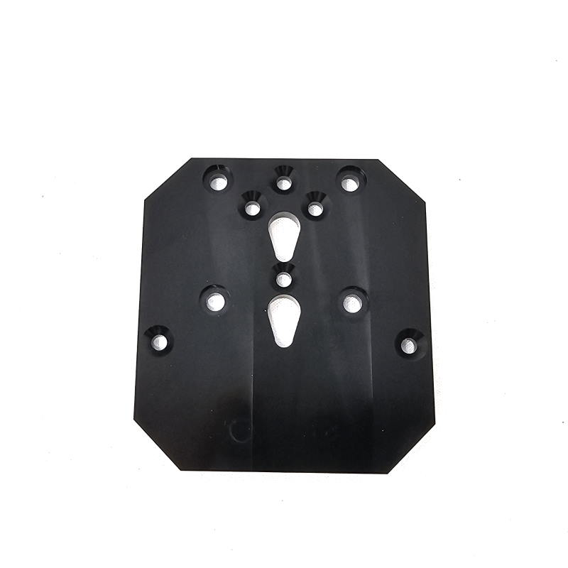
- Clear/Generic Mount — if you have a custom mount or want to adapt the mount yourself.
Tip: If you already have a router installed and want to keep it, the front‑mount or router clamp mount gives the most flexibility.
Step 2: Mount the Laser Head
- Power off the machine, disconnect power, and lock out/unplug any spindle or router power.
- Using the mounting hardware provided: attach the laser mount to your Z‑axis/spindle holder according to your chosen option.
- If front‑mount: clamp or screw the two‑piece mount to the front face of the spindle holder (per the “Front Laser Mounting Kit” instructions).
- If 80 mm clamp mount: secure the laser under the spindle shell, ensuring clearance for travel and any dust‑boot.
- If router clamp mount: with router lowered all the way, mount the laser bracket underneath the router body.
- Attach the laser head into the holder, align so that the output lens is centered over your work area and the gantry can move freely without interference.
- Route the laser head cable(s) cleanly: use included zip ties and holders so that the cables move safely with the gantry and do not catch on the drag chain or frame.
Step 3: Mount the Laser Driver / Interface
- Choose a stable location for the laser driver / safety interface board—ideally mounted near your machine’s controller, but off the moving gantry.
- Ensure the driver location is clean, dry, and with enough ventilation (laser drivers generate heat).
- Use the sticky squares or mounting screws provided in the kit to secure the driver board. J Tech Photonics, Inc.
- Route the extension cables (if you selected them) from driver → gantry movement path → laser head. Measure the distance carefully and choose the correct extension length (5′, 10′, 15′, 20′, 25′) to avoid tension or slack. J Tech Photonics, Inc.
- Leave slack in the cable at the gantry pivot so that movement will not pull or stress the connector.
Step 4: Wiring & Connections
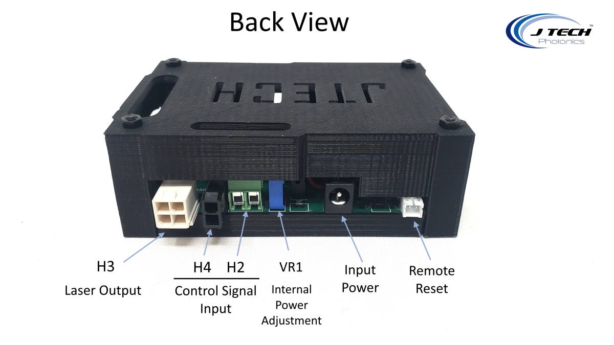
- Power input: Connect the power cord from the kit to the driver board. Make sure the voltage and plug option match your region (US, UK, EU, AUS) as selected.
- Laser head connection: Plug the laser head’s Molex Mini‑Fit Jr connector into the driver (or extension) cable. Make sure the connection clicks firmly.
- Control input from CNC controller: Connect the control signal cable from your CNC controller board (for example under the DRV board or I/O board of your CNC4Newbie machine) to the signal input on the laser driver/interface board. Refer to your CNC controller documentation for proper pin (usually a PWM or TTL laser enable output). See Step 5 for more details.
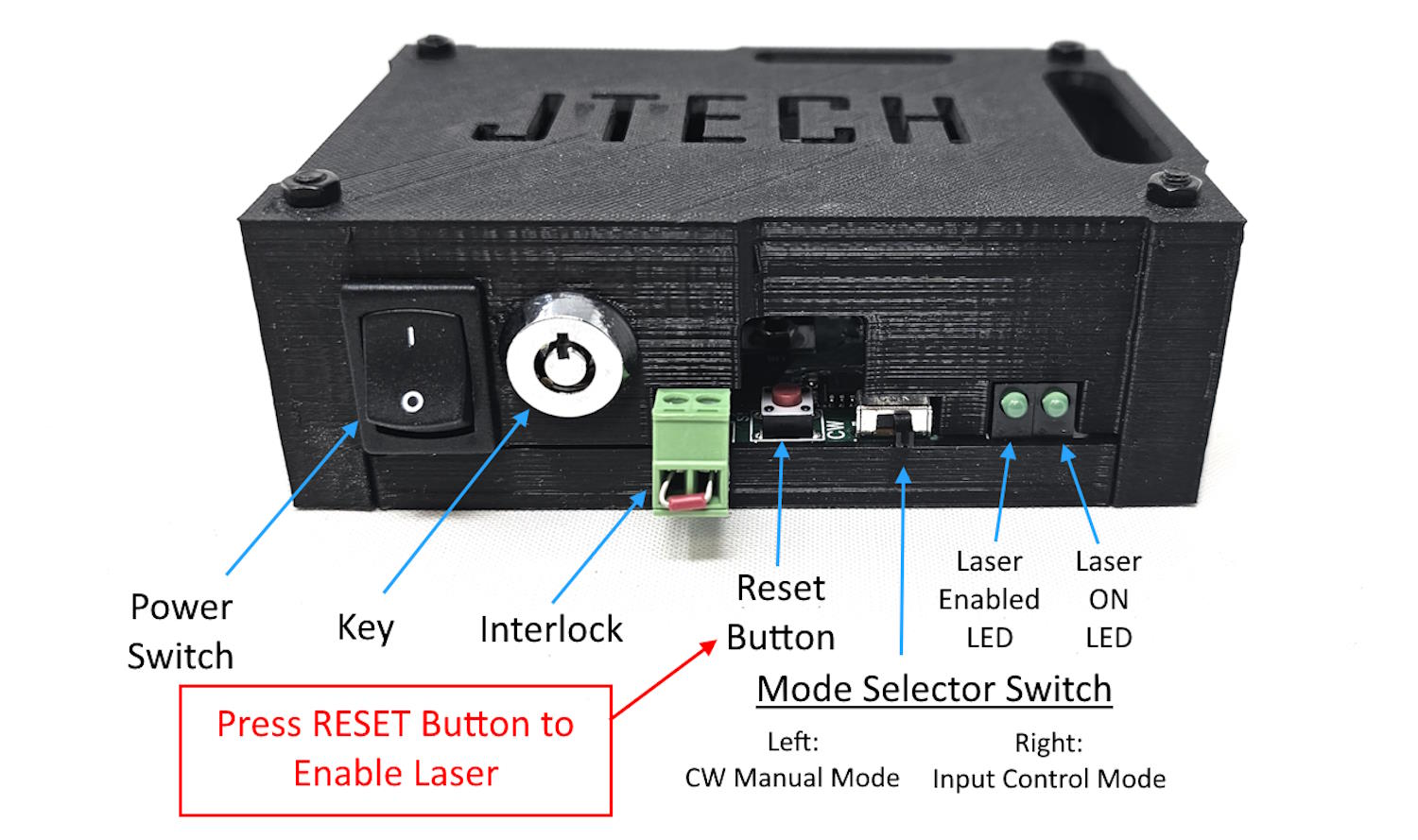
- Safety interlock (if desired): Your kit has a key switch and also a remote interlock option (for enclosure doors, emergency stop, etc.). Use the screw terminals for the interlock in the front of the safety interface board.
- Double‑check all connections: driver power, signal input, laser head output, extension cables, interlock wiring.
Step 5: Wiring to CNC Controller
Depending on which controller you have with your CNC, it will be different wiring. The molex cable that is included in your bundle will be able to connect to your specific controller.
Demon Controller (Best Option)
The Demon controller is the easiest option as it uses GRBL for it’s control system. All you need to do is connect the input cable to the screw terminals marked “PWM”. You can then use the Lightburn Setup video to configure your machine.

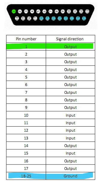
UC100
The UC100 uses a DB25 connector which you can attach a breakout board to it. You can purchase on on Amazon here: https://www.amazon.com/dp/B00SUINB2S
We recommend using the Pin 1 output and any connection from 18 to 25 for the ground pin.
Step 6: Software Setup
If you are using the Demon controller, you can use Lightburn as your software to run your machine. You can find it at Lightburnsoftware.com.
Follow the video here to set up your software:
If you are using Mach3/4 or UCCNC, then follow the other instructions on our page to set it up.
- Mach3 Instructions
- Mach 4 Instructions
- UCCNC: Set your “laser pin” to the output on the UC100 that you want to use and configure the output as a PWM Spindle in the AXIS tab. For example, you might use the output #1 from your UC100 for this. Another option is to use the UC100 pin 17 as the laser pin and the output 1 as the spindle relay pin. In the IO setup tab, you select your laser pin then as pin 17.
Step 7: Typical Mounting & Focus Tips
- Ensure the laser head is pointed down to the work surface for the best engraving/cutting quality. The higher power lasers will not fire if they are not pointed down.
- Verify the head can traverse your full intended area without intercepting clamps, rails or stray objects.
- Use the extension cable length appropriate for your machine size to avoid cable drag or gantry strain.
- If you selected air‑assist (it is included in the higher wattage models: 24 W, 44 W, 64 W), connect the hose and nozzle and supply consistent air pressure (approximately 10‑25 psi) for cleaner cutting and reduced char. Or use the pump recommended here: Aquarium Pump for Cutting and Engraving (Choose the 55W Pump) ALWAYS USE THE AIR ASSIST WHEN USING THE LASER AS NOT TO BURN THE LENS
- Label your wiring for future maintenance—especially signal wires (laser enable, emergency stop, interlock).
Safety Reminders
- This upgrade involves a Class‑4 laser system. Direct or reflected beam exposure can cause permanent eye damage or skin burns.
- Ensure the work area is well ventilated; cutting certain materials may generate hazardous fumes or particulates.
- Use proper shielding if other people are in the vicinity. Ensure that bystanders wear goggles or stay behind protective barriers.
- Never leave the laser running unattended.
- Use the key switch and interlocks provided to disable the laser when you are not operating.
- Always follow the full safety guidelines included with your kit.
- For any uncertainties regarding wiring or configuration, stop and contact our support team at [email protected]
Troubleshooting Quick‑Guide
| Issue | Possible Cause | Action |
|---|---|---|
| Laser will not fire | Key switch off or interlock open | Check key switch, interlock wiring, reset driver |
| Gantry motion causes cable snag | Cable length too short or not secured | Adjust routing, use correct extension length, add slack |
| Poor engraving quality or cut | Focus incorrect, head not parallel, speed/power wrong | Re‑align head, verify Z‑height, run test burn, adjust settings |
| Laser fires but no output or very weak | Wrong driver current, lens dirty, air‑assist blocked | Check driver current setting, clean lens, inspect air flow |
| Machine controller does not trigger laser | Incorrect output pin, firmware setting wrong | Verify controller pin assignment, ensure “Laser mode” enabled in software |
Congratulations, You’re Ready!
Once you’ve validated motion, focus, and a test burn, you’re ready to start using your J Tech laser upgrade on your CNC 4 Newbie machine.
Feel free to experiment with engraving depths, vector cuts, and new materials—just remember to operate safely.
If you run into any issues, our team is ready to help: support at [email protected] or sales at [email protected].
Happy manufacturing and have fun creating!
— The J Tech Photonics Support Team