


The Rich Auto DSP controller is used in a lot of various CNC machines. It is a DSP based control system that contains a small circuit board located in the CNC machine control box and a pendant system that is connected via a cable.
We are going to go through how to connect a our laser upgrade kits using the spindle output from the controller. This upgrade will require getting a DPST switch to switch between the laser and the spindle mode due to the relay on the spindle. This is an easy upgrade and will get you up and running with your laser in no time. You will then just need to figure out how to mount the laser on your machine. Let’s get started!
Electrical
In the control box of your cnc machine, there will either be a little blue circuit board or a black controller. The newer version of the RichAuto DSP controller will be packaged in a metal box. The older versions will have a “0501” in the name, while the newer ones will have “A11” in the name. It will be the same method to connect either way, so no problem there. Here are some pictures of the controller.
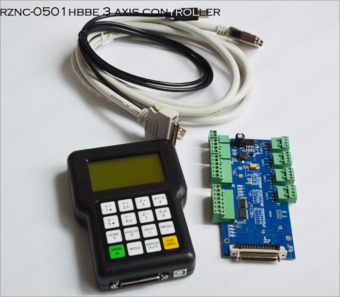
Older systems Rich Auto Controller
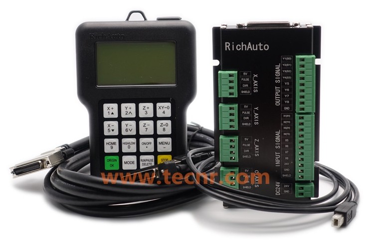
Newer version of the RichAuto DSP controller
There is a section of outputs on the board that are for the spindle control. It is on the top right connector. Here is the picture of the older style controllers:

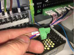
Here is a picture of the newer “enclosed” version of the controller:

Most machines will have a “spindle relay” that is controlled by the Y1(S0) signal. Your machine diagram will look like this how it is before the laser.

Since the laser will turn on and off a lot of times, you want to not have the relay for the spindle turning on and off this much. So we will ADD a SPDT switch to the circuit so you can switch between the laser and the spindle.
Here is the wiring diagram for this:

Here is a diagram of the switch:

Step By Step Instructions:
- Find the Y1(S0) wire.

2. Take the wire that was in the Y1(S0) connector and connect it to the SPDT switch on the SPINDLE side. 3. Now the Y1(S0) is empty. Put a NEW wire in this connection and put it to the middle of the SPDT switch. This is the signal input for the switch.

4. Take the NEGATIVE (Black) signal from the Laser Driver input connector. If you use the SPDT switch, then this will be on the LASER side of the switch.
3. Find the +24 terminal on the RichAuto controller. Insert the POSITIVE (Red) signal from the Laser Driver input connector into the +24 terminal. There probably is going to be another wire there. Do your best to get both of them in the same screw terminal.
Now that you have it all connected, lets go over what you need to know about configuring the controller.
Controller
The RichAuto system has a pendant for control. You will need to navigate some of the menus to make a couple of changes to get the laser to work properly.
When the Laser is to be used the Spindle Delay will need to be set to Zero. Spindle Delay allows the spindle 4 seconds of warm up time to reach the proper speed before beginning the operation. Unfortunately, if this is not set to Zero, the laser will sit for 4 seconds after activating before beginning the engraving process.
To change this setting:
- From the main coordinate screen, Press MENU.
- Machine Setup should be highlighted. Press OK to select.
- Scroll down to highlight the Spindle Setup. Press OK to select.
- Highlight Spindle Delay. Press OK to select.
- The Spidle Delay settings will be displayed. Highlight the Spindle ON setting and press the Delete button.
- Enter the new parameter of (0.00) and press OK.
- Do the same for Spindle OFF and make sure it is also set to (0.00).
Once finished, press the Stop/Cancel button until you have returned to the main coordinate screen.
Mechanical
This controller is used on a lot of different machines, like the Laguna CNC and OMNI to mention a couple. We recommend putting the laser driver close to the controller box, or even in it. Then you can measure the distance needed to get through the cable chain to the gantry. The laser and fan extension cords are here:
Details on the laser mounting holes and dimensions are located here:
And there it is! Let us know if you have questions!
Click Here to Buy your laser upgrade kit now!

Remember Safety First!

We sell laser shielding to block laser radiation and reflections!
Laser Goggles are also a must!
Disclaimer
The laser used in this project is very powerful and all safety precautions must be taken. Use proper safety eyewear to prevent injury to eyes. This is a project and J Tech Photonics, Inc. is not responsible or liable for any and all damage or injury caused to people or property. The use of these instructions to make a laser cutter is under your own discretion and all safety precautions should be followed. J Tech Photonics, Inc. is not affiliated in any way with RichAuto DSP and they may change the hardware at any time making these instructions invalid.