


 Learn About Our Custom Lulzbot Mini Laser Conversion

We recently got a request to complete a full conversion of a lulzbot mini into a laser machine. We love printing with our lulzbot, but it is even cooler as a laser machine! The post details the conversion process in case someone else want to perform it for themselves, and also shows how to do a laser upgrade for the electronics in case you want to complete it without removing your extruder. We will also post these as instructions on a seperate page to detail how to upgrade your Lulzbot Mini or Taz style printers with the Rambo board.
So let’s get started!
Electronics
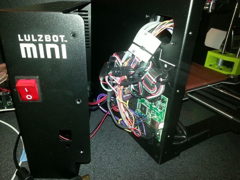
We are going to use the fan1 connection on the Rambo board to control the laser. It has PWM control needed to do picture engraving and is easily controlled with M106/107 commands in software. We decided to remove the extruder assembly to get more room for the laser on the worksurface, but left the actual extruder on the Z axis because the firmware looks for it on startup. We choose to mount the driver on the side of the enclosure because the enclosure is full of electronics already and it is easily accessable for the key switch and power controls without having to put more holes in the alluminum. We routed the laser and fan cables through the enclosure and up the wiring harness chain to the Z axis and made it all nice and tidy.
Mechanical
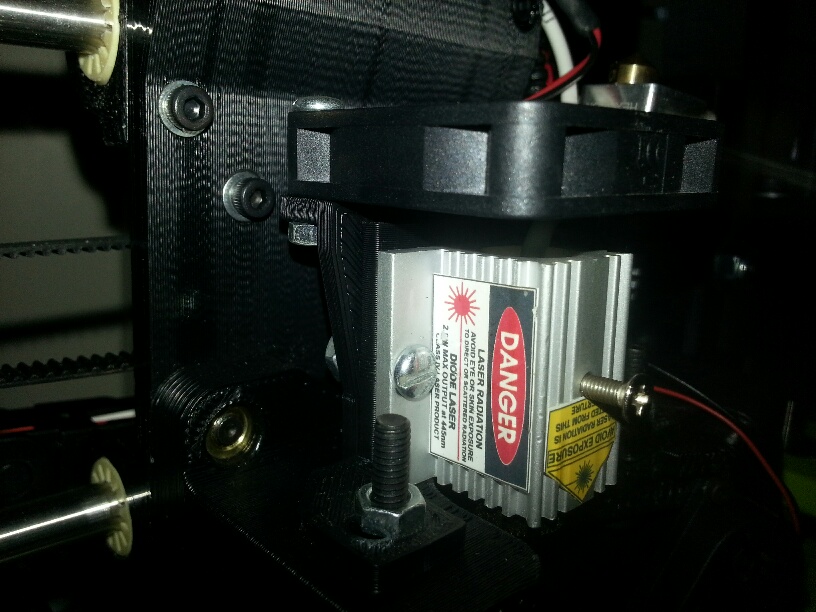
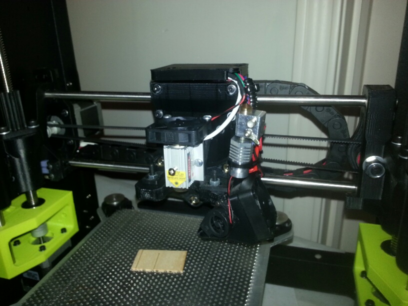
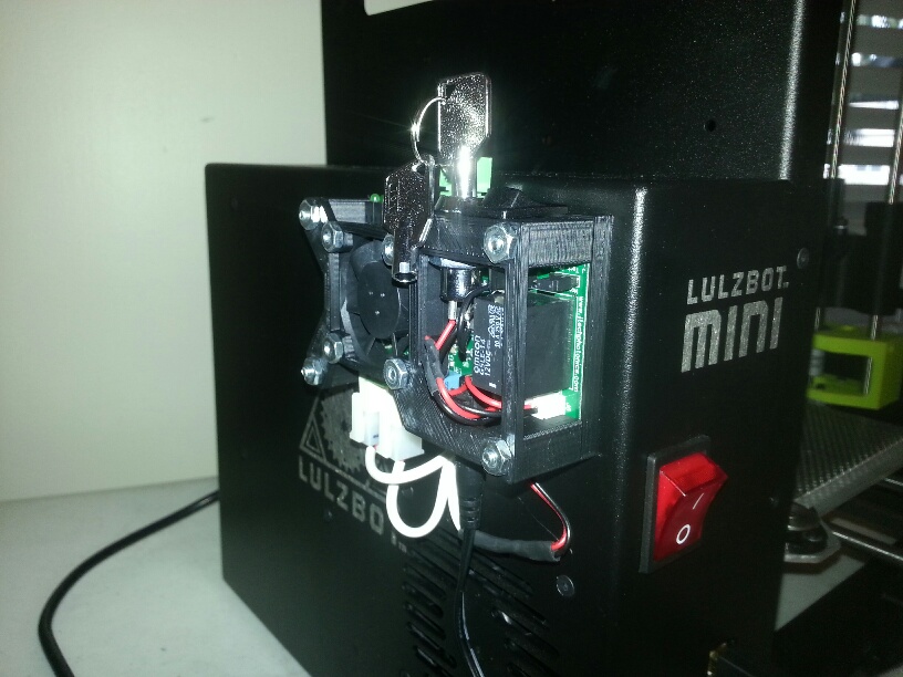
We made a mount to fit using the screws that attached to the extruder assembly we removed. It allows the laser to point down on the work surface and have the same position as the old extruder. This gave the maximum table size for the laser without having to limit anything. The mount for the laser is here:
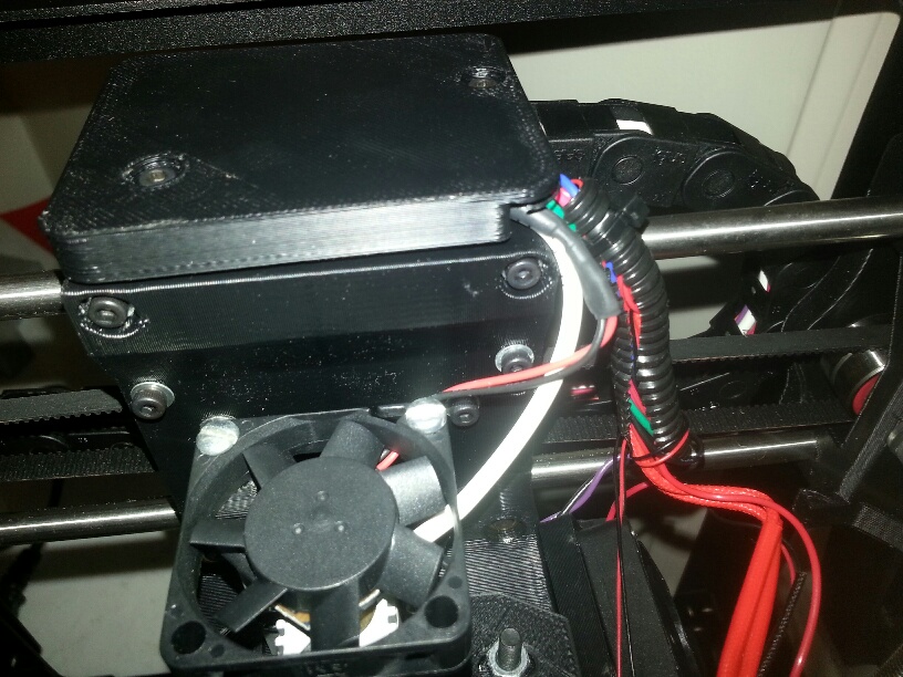
The fan upgrade kit fits on the back of the laser and nothing was needed for modification.
We also removed the glass table and replaced it with a 6″ x 6″ piece of aluminum we bought from Amazon small parts. Considering the laser can burn through the glass surface, we choose to put an aluminum bed instead. We made small mounting holders for each of the corners to keep the aluminum held down to the table. It would be better to make a piece of aluminum to fit that is 7″ x 7″ but we didn’t have the time to cut a piece ourselves due to our CNC being unassembled (more on that later). Here is a link to the mounting holders:
Software
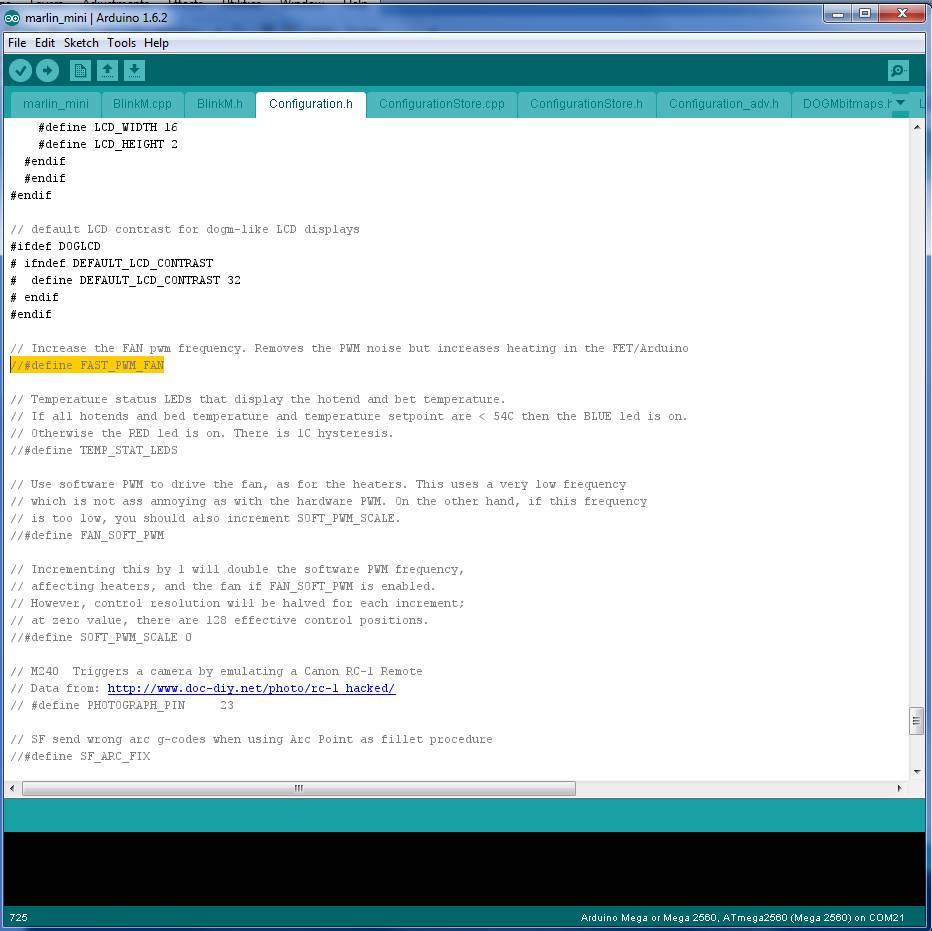
We had to modify the firmware of the Lulzbot because the PWM frequency was set way to high for it to control the laser. You can get the firmware from Lulzbot here:
You need to load all of the files into your Arduino compiler and make a new sketch that shows all of the files. Make sure you have the newest version of the compiler downloaded from Arduino HERE. Set you board as Arduino Mega or Mega 2560 . Then in config.h, comment out the line:
//#define FAST_PWM_FAN
Then make sure your are connected to the correct COM port and the printer is connected to the computer and compile the firmware. You are now done!
We used Repetier Host to control the printer. We like the “preview” feature for the G Code and it does a good job with everything else as well. You need to adjust some of the settings because the table will be slightly smaller. Here are instructions for the configuration:
Lulzbot Laser Setup Instructions
Ok, now let’s get to the upgrading with pictures!
Step By Step with Pictures
1. Open the Box. I like that it says Open on the top…
2. Print out the little tab for the aluminum plate on the bed. Total of 4.
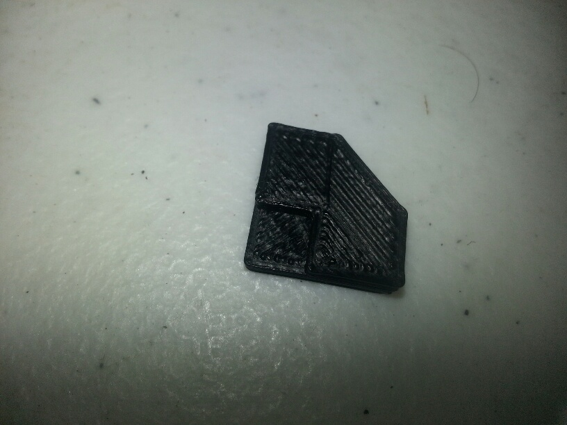
3. Place the tabs on top of the aluminum plate. Remember, you only need this if you bought the 6″ x 6″ aluminum sheet.
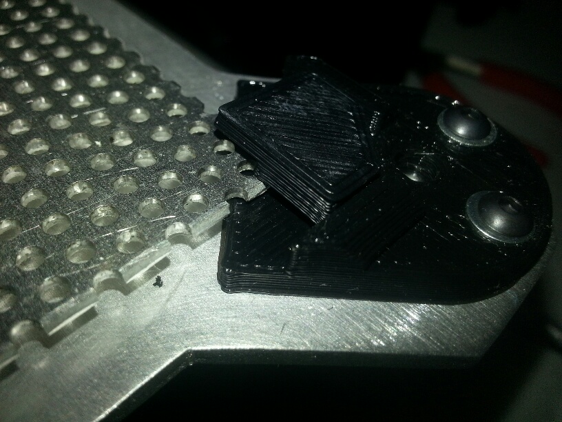
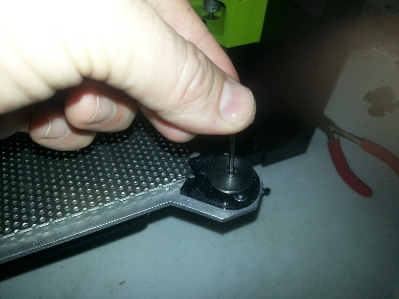
4. Screw on the top metal circle to hold the plate down on all four sides.
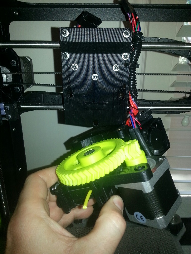
5. Take off the extruder assembly. Three screws from the back side and uplug it from the top connector.
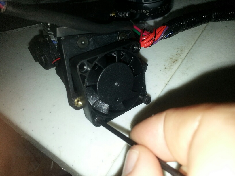
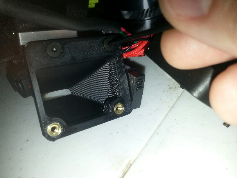
6. Take off the fan.
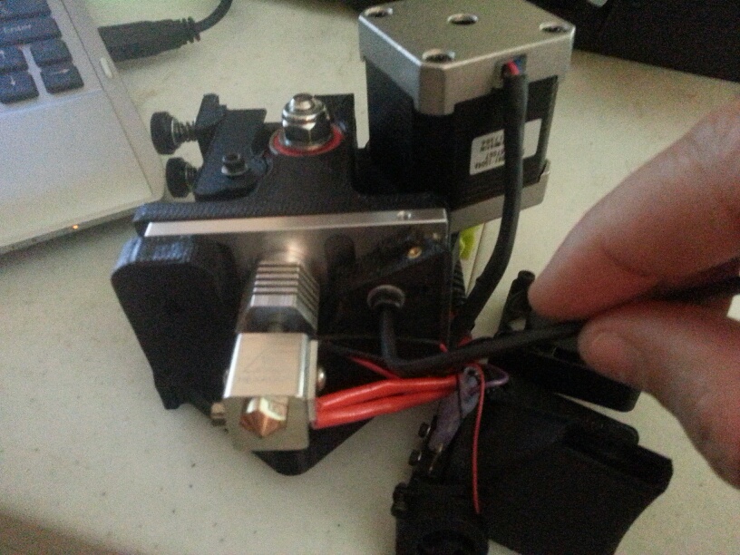
7. Take off the nozzle attachment.
8. Remove the extruder motor assembly with two screws shown on each side of the extruder.
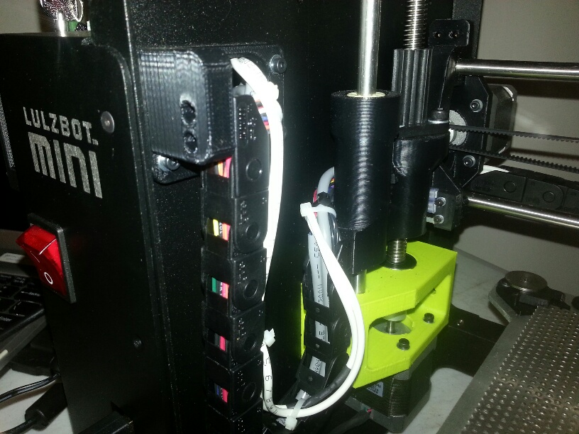
9. Mount the laser mount using the extruder screws in the laser step. Mount the laser to the mount and also the fan upgrade mount.
10. Cut the motor cable and put extruder motor assembly aside. Keep the extruder and zip tie it in place. Route the cables up and through the back wire chain.
11. screw down the top after the wires are routed.
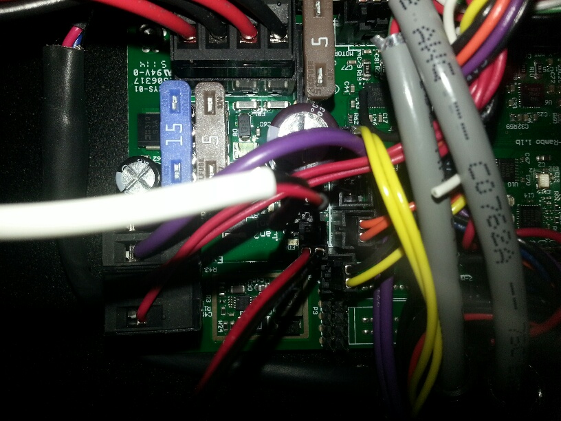
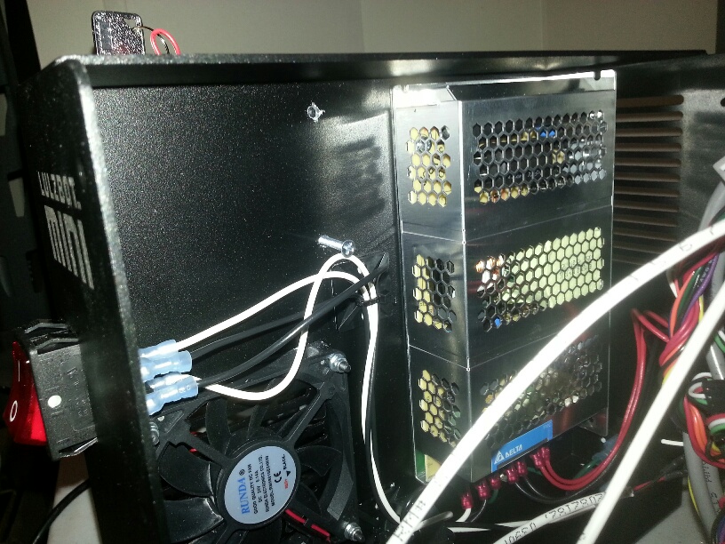
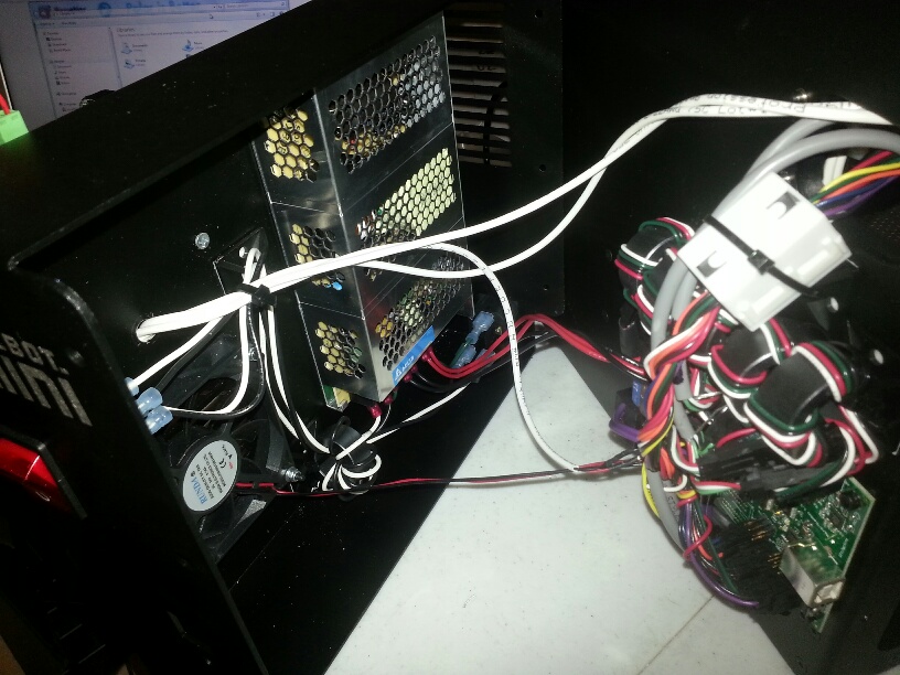
12. Open the electronics enclosure.
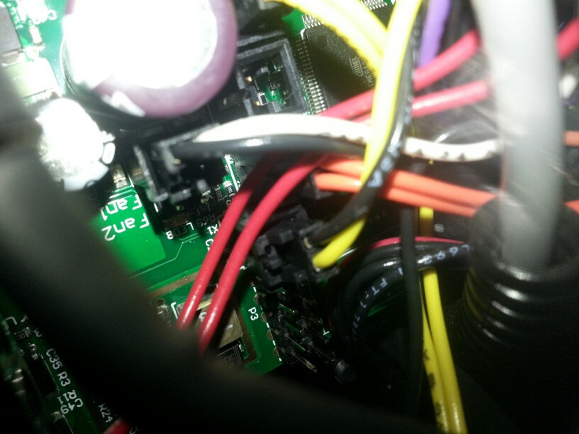
13. We will be using the FAN1 connection to connect the laser. It is the Black and White cable.
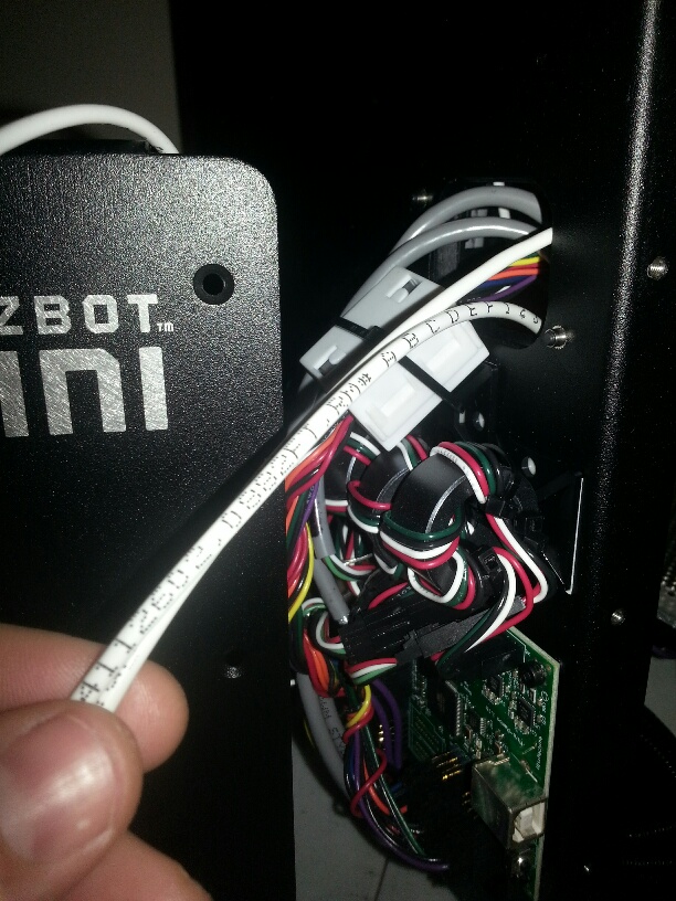
14. Put wires into enclosure and zip tie on the cable chain.
15. Pull wires through into the enclosure.
16. Replace fan cable with new cable to laser driver. We cut our fan cable and soldered a longer cable onto the original connector.
17. Drill holes to mount the laser driver board on the outside of the enclosure. Drill one, then put the driver board up and mark the rest to line it up.
18. Drill larger hole for laser, fan, and control cables to the laser driver board and route.
19. Mount the laser driver and connect the laser, fan, and control cables.
20. Open the Arduino SW and load the Marlin Mini firmware. In config.h, comment out the line FAST_PWM_FAN like in the picture. You can also use SW PWM, but make sure it is not above 5KHz.
21. All done and ready to engrave and cut!
Hi- what would be involved if I wanted to do this with the full sized Taz 4? Thanks-
There is not much different. We put new instructions on upgrading both the mini and the Taz here: https://jtechphotonics.com/?page_id=2438
The only difference is you need to update the Taz firmware if you want to have PWM control for photo engraving.
What’s the cutting capacity for something like this? (going to do it on a Taz 4).
It can cut non-dense wood like balsa and basswood, cast acrylic sheet that is not transparent, many types of foam including the pink home depot insulation foam, cardboard, and paper. It can engrave on many other items as well. Check out the applications here: https://jtechphotonics.com/?page_id=1177