

These are the OLD Version instructions. To see the newest version for the PRO Series laser machine, go to:
The OpenBuilds ACRO rail system is a great system for using our lasers with it. We have put together a full package for the a J Tech Photonics version with the mechanical, motion control, and the laser portion of the machine. We get a lot of people who want to build a small and easy to use machine that does not have a router attached to it to run dedicated with just the laser. Well, here it is!
Let’s get started on how to put it together.
Step By Step Instructions:
First, you need to assemble the rail system and then put on the electronics and cable chains. We have made many changes over the last year to the Z stage and cable chains on the system. We have updated the changes in the video in this document. We will be updating the videos shortly, but in the meantime, use the following document as a guide.
Download These Instructions To Go With The Videos
Mechanical Video Instructions
J Tech ACRO Mechanical Instructions
Electrical Video Instructions:
J Tech ACRO Electronics Instructions
Lighturn Software Setup:
Running Your Machine
Software Options
Now that you have put your machine together, there are a lot of options for how to run it. It will depend on what software you might already have and if you want to purchase any new software or not. We HIGHLY Recommend getting the Lightburn software package as it will run the entire process and make it the easiest to use your machine. We will be doing all of the rest of the instructions with this software. However, since this machine is based on an open source controller architecture, there are a lot of choices out there. We cover Lightburn in detail here. At the end of the instructions, you can find more option for free and paid software programs.
All in One Software Package:
- Lightburn Software – *recommended* This is an “all in one” software package that you can do vector art, import SVG files, engrave images, and run the machine all in one place. We recommend using this software as it will be the easiest to use and run the machine. You can get it here:
Set Up Your Machine
Ok, now that you have downloaded Lightburn software, we can get started with the rest of the setup. If you are using another software package then you can follow along as well. When you install the Lightburn software, you might see Windows trying to protect you. Click on the bottom “Run Anyway” button to install it.
When you first run Lightburn, you should have a quick setup wizard walk you through the setup. Here is what you need to do to get it set up.
- Choose GRBL from the list:

2. Choose Serial/USB

3. Name your machine and put in the dimensions.

ACRO 55 : X Axis = 420mm Y Axis = 350mm
ACRO 510: X Axis = 920mm Y Axis = 350mm
ACRO 1010: X Axis = 920mm Y Axis = 850mm
ACRO 1510: X Axis = 920mm Y Axis = 1350mm
ACRO 1515: X Axis = 1420mm Y Axis = 1350mm
4. Choose your origin and unclick “autoHome”

5. Click on “Finish” to complete setup

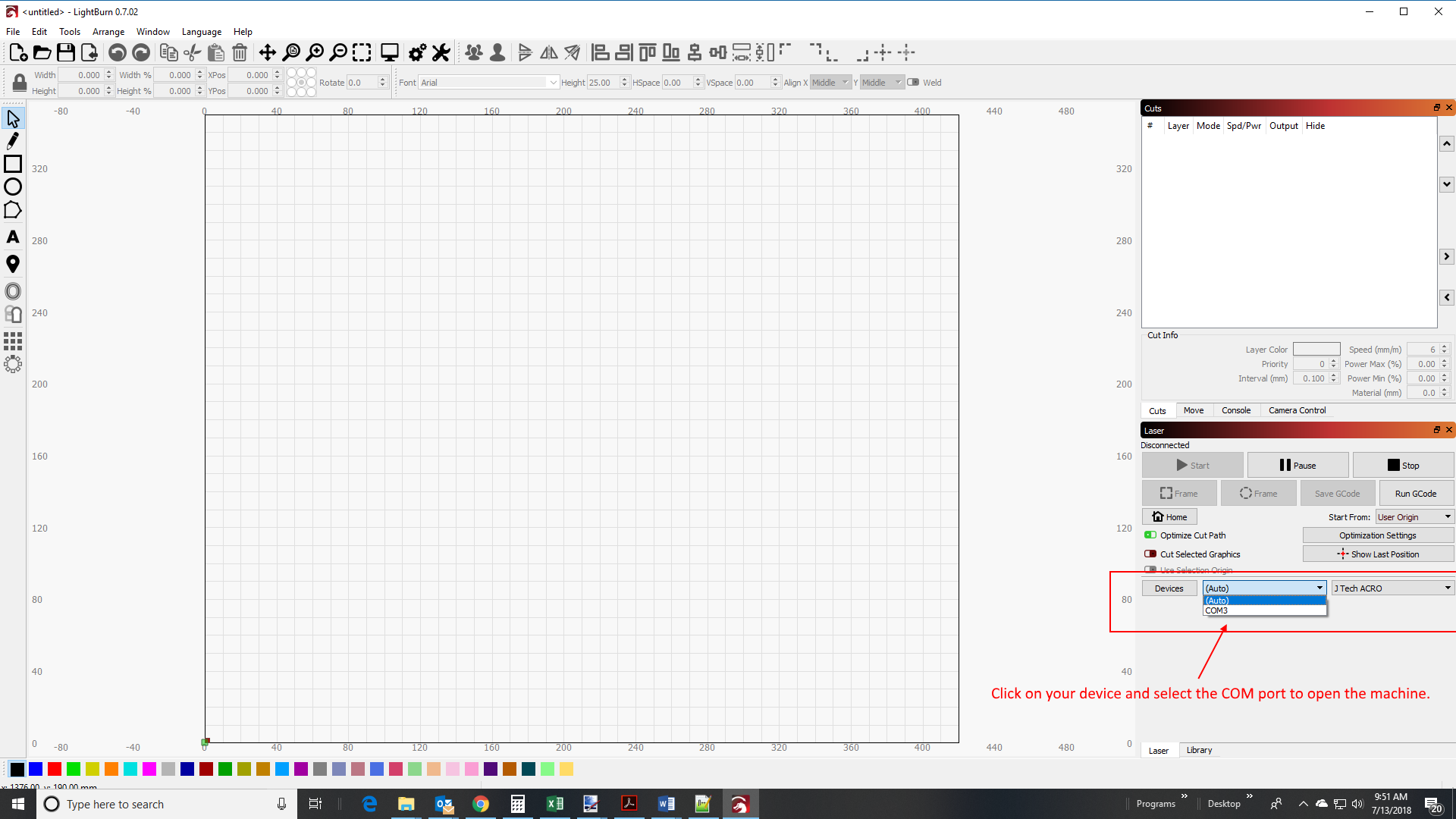
6. Connect to the machine
Click on the bottom right to select your machine from the drop down and click on the COM port to connect it. Make sure the USB cable is attached and the power to the machine is on (plugged in).
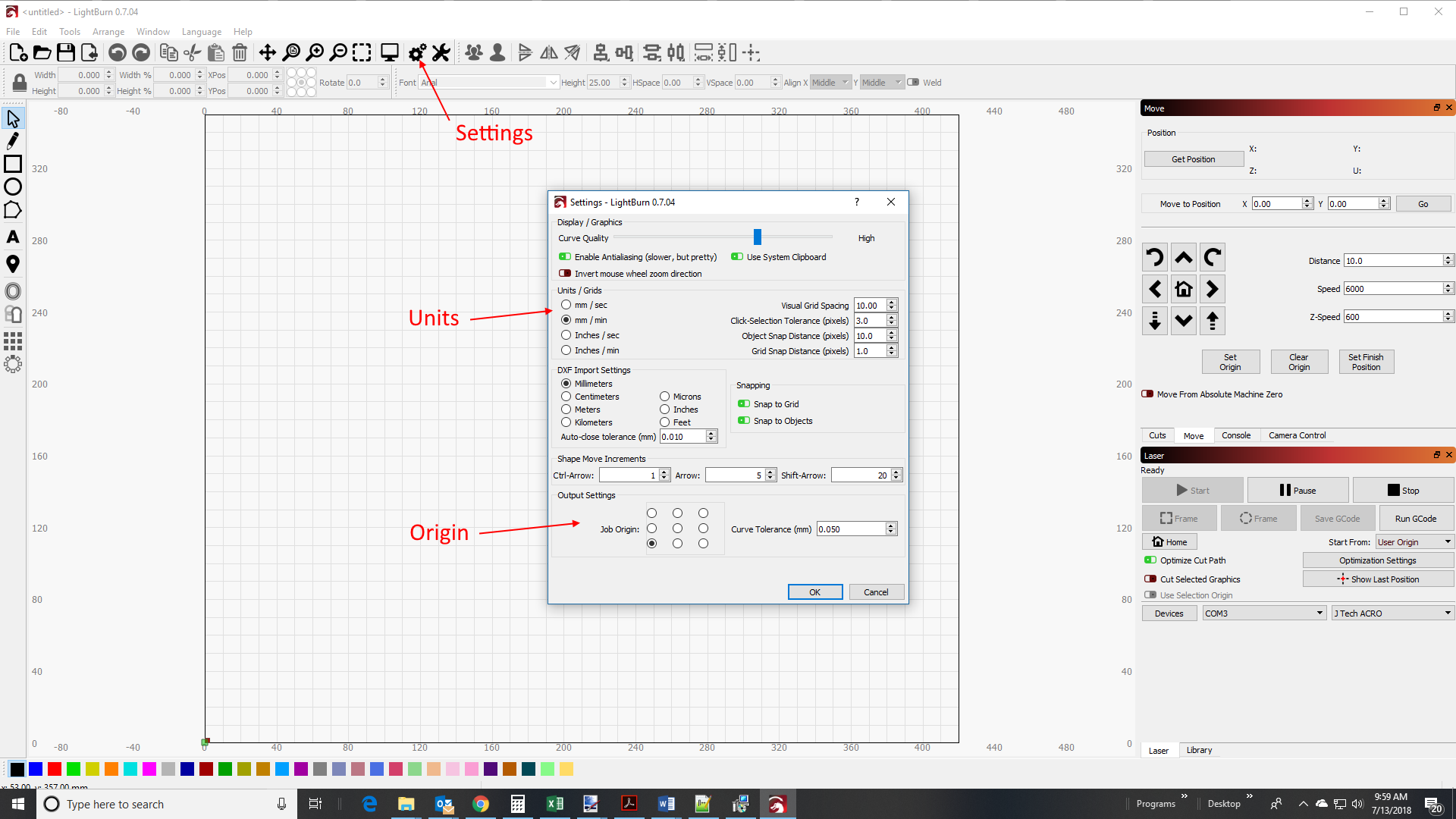
7. Choose your settings
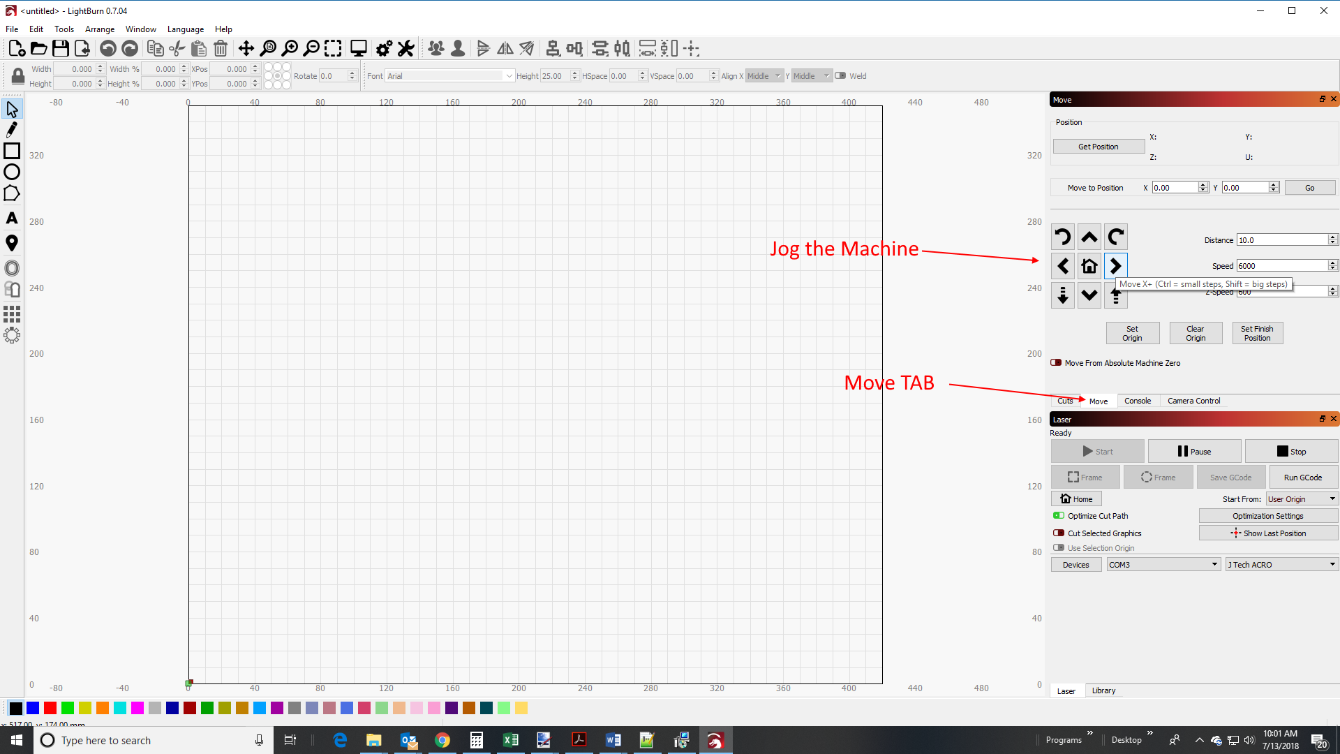
8. Jog the machine to check the AXIS are set up correctly.
9. Change Settings or Motor Cables
If your Y axis does not move, then you have one of the Y axis motor cables backwards.
-Turn off the machine
-Unplug either the Y cable or the A cable on the GRBL Controller
-Flip the cable over
-Plug it back in
Check the Y Axis again and see if it moves. It should be a smooth movement.
Check the direction of all of the movement. If an axis moves the wrong way you can flip the motor cable on the GRBL controller of change it in the firmware.
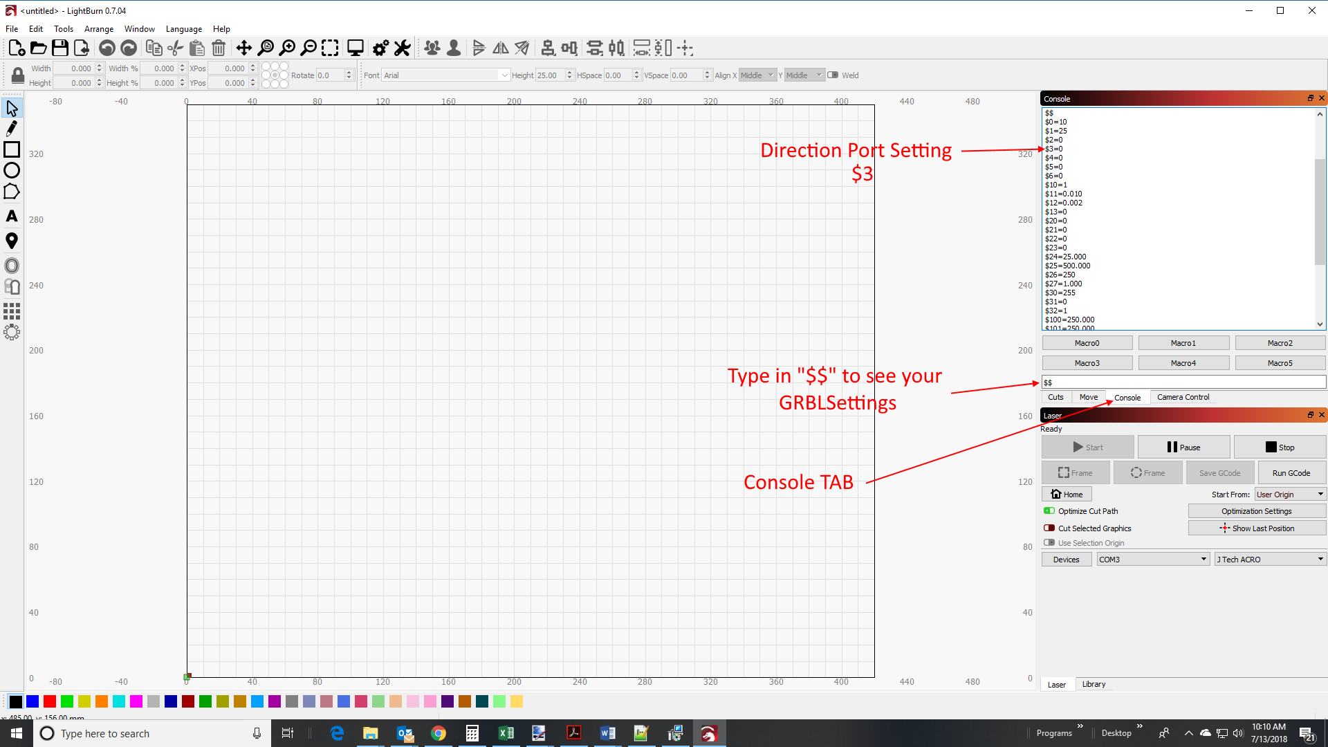
If you rather change it in the firmware, then use the table to put a new value in for $3.
| Setting Value | Mask | Invert X | Invert Y | Invert Z |
|---|---|---|---|---|
| 0 | 00000000 | N | N | N |
| 1 | 00000001 | Y | N | N |
| 2 | 00000010 | N | Y | N |
| 3 | 00000011 | Y | Y | N |
| 4 | 00000100 | N | N | Y |
| 5 | 00000101 | Y | N | Y |
| 6 | 00000110 | N | Y | Y |
| 7 | 00000111 | Y | Y | Y |
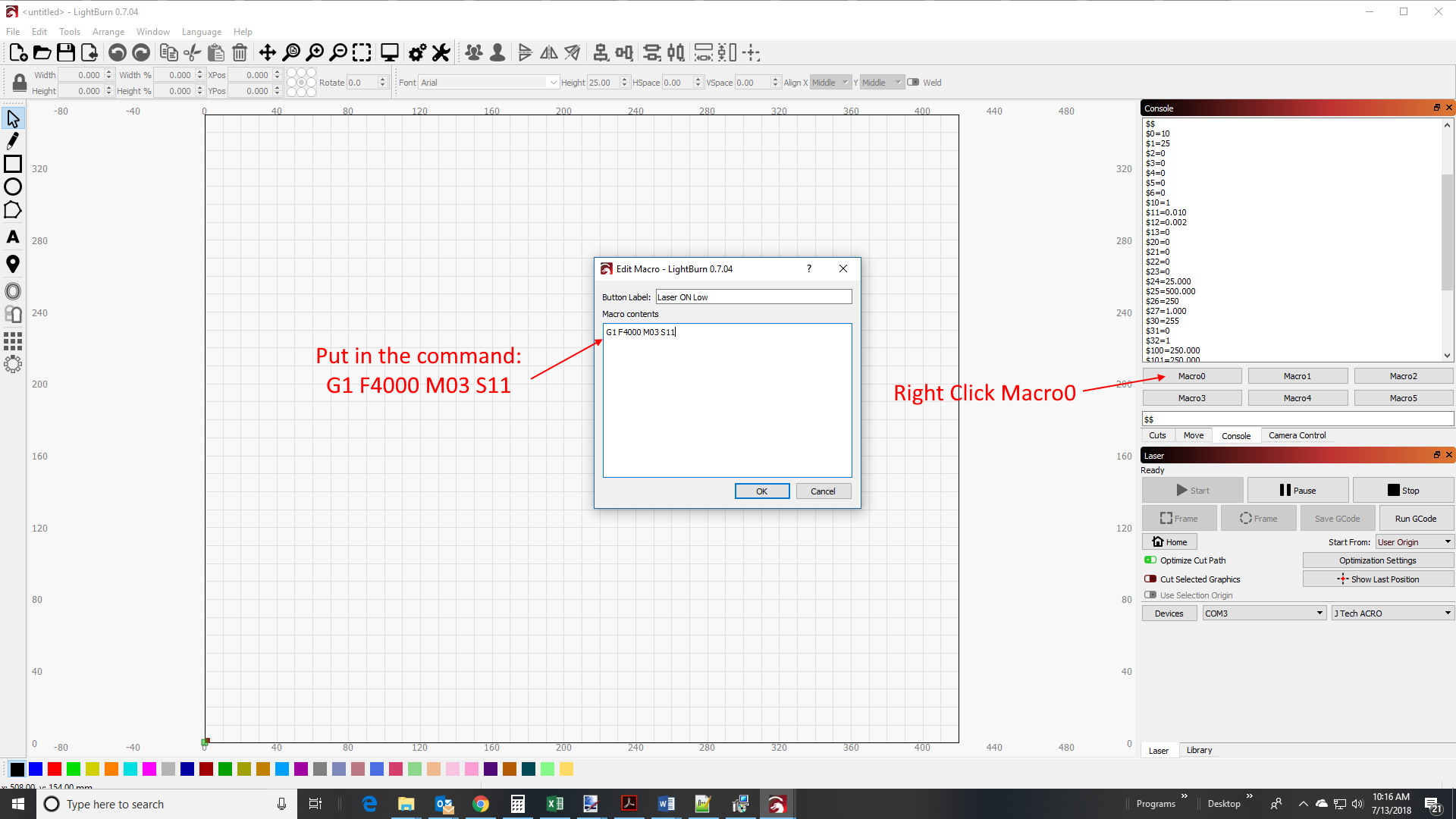
10. Put in low power macro
It is always nice to see where the laser is on low power to make sure you are lined up with your work piece. Let’s put in a macro to turn this on.
Right click on the Macro0 button to be able to change it.
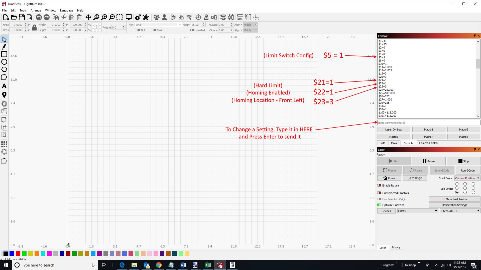
Lightburn Limit Switch Configuration
If you choose to put limit switches on your machine, we will need to change some settings in lightburn.
- Change your settings to enable homing to the front left corner.
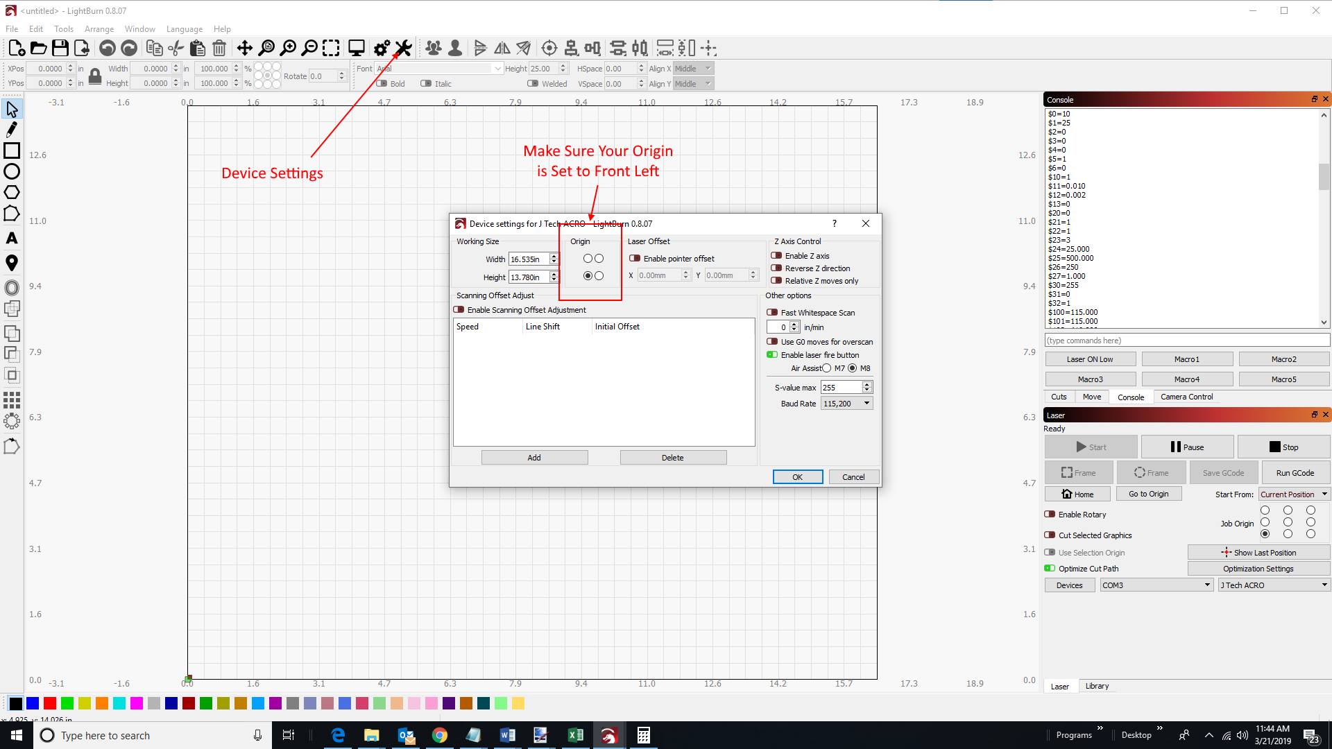
Make sure your origin is in the front corner.
Set your offset to zero in your machine parameters. Type in the console: “G10 L2 P1 X0 Y0 Z0”.
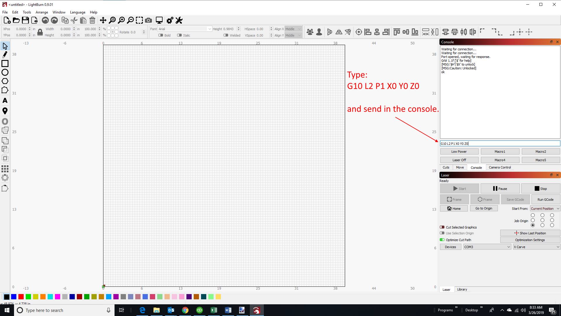
Check your offsets by typing “$#” in they should all be zero.
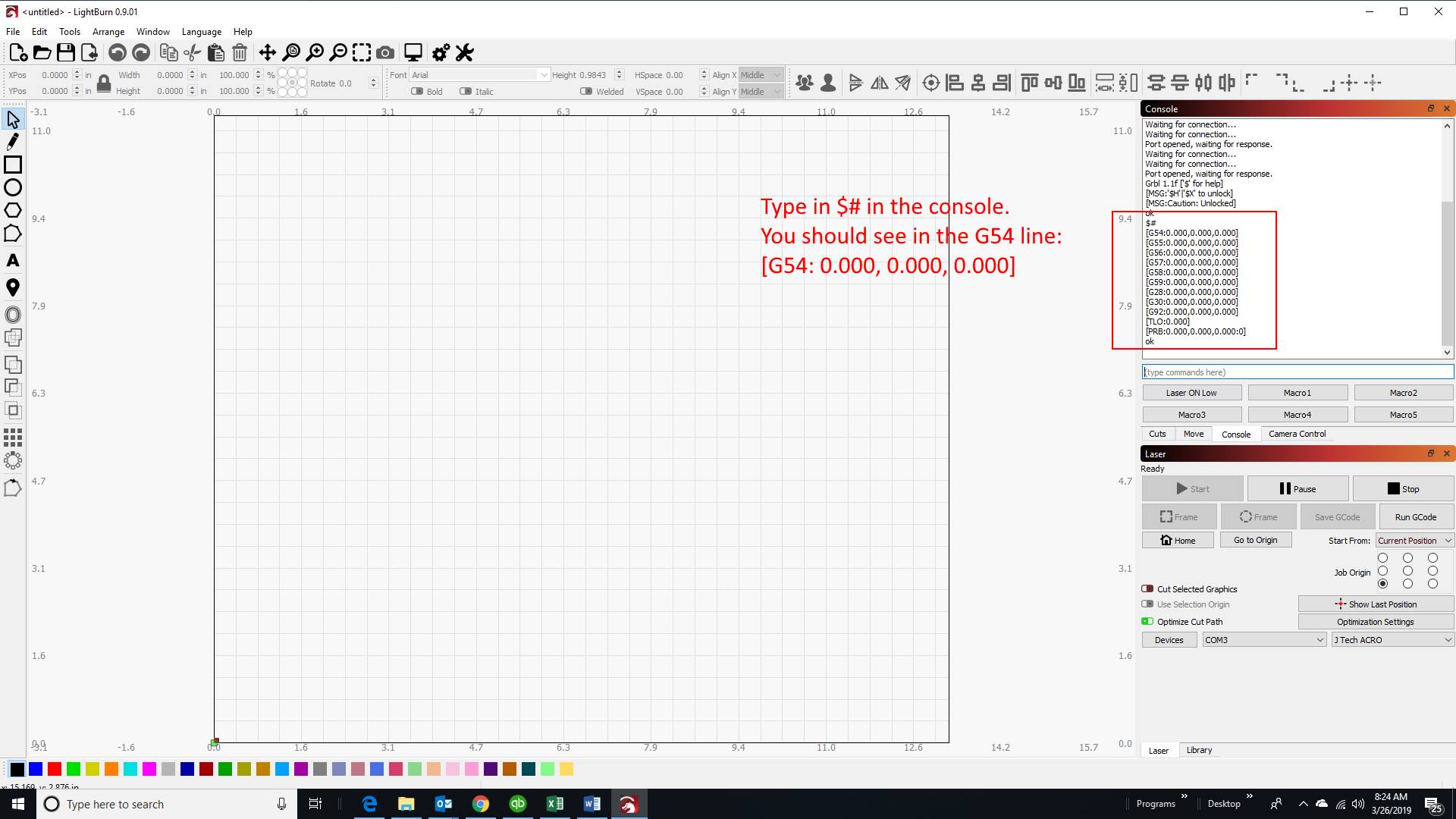
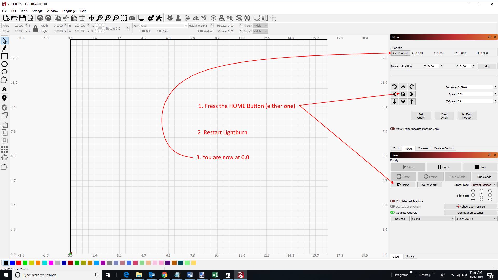
Try homing your machine. You will need to:
– Press the Home Button. Your machine will home to the front left corner of the machine.
– Restart Lightburn. Your machine will now be at 0,0,0.
You are now all set up! We are ready to really start using the machine now. Let’s dive into some of the features of the Lightburn software.
Using Lightburn Software
We will walk through a quick engrave just to get started and then we will run it on the machine.
1. Click on the Letter Tool and write “Hello World”
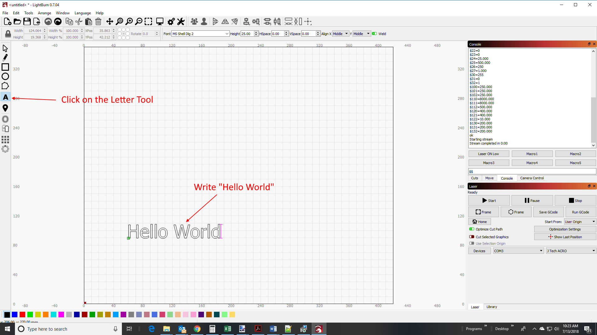
Notice the origin (little greet dot) is on the bottom right. This is where it will start the engraving from.
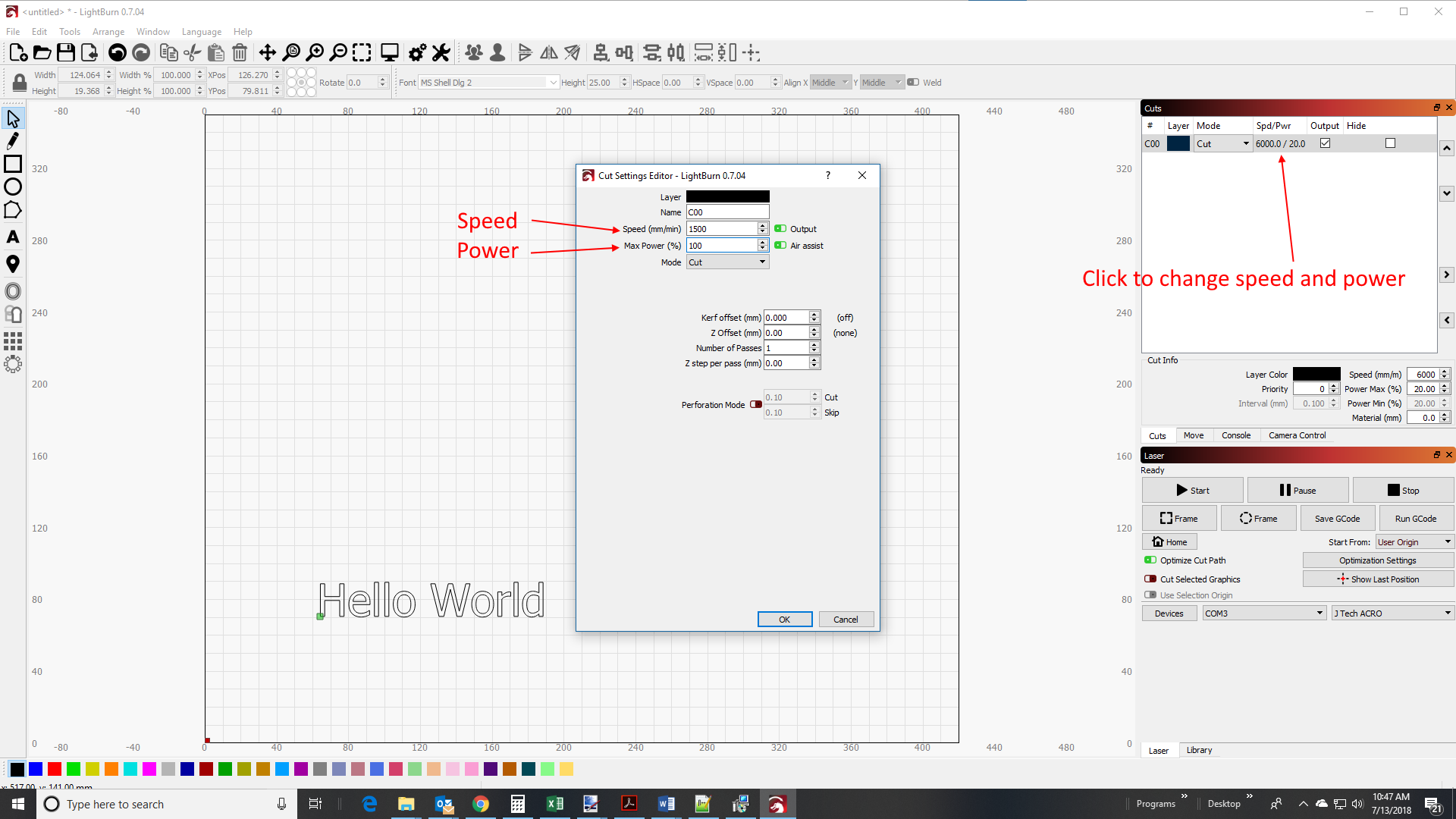
2. Set the Cut Power and Speed
Click on the arrow tool. You can highlight the text and move it around if you want. Click on the CUTS tab on the right and notice there is a black layer for the text.
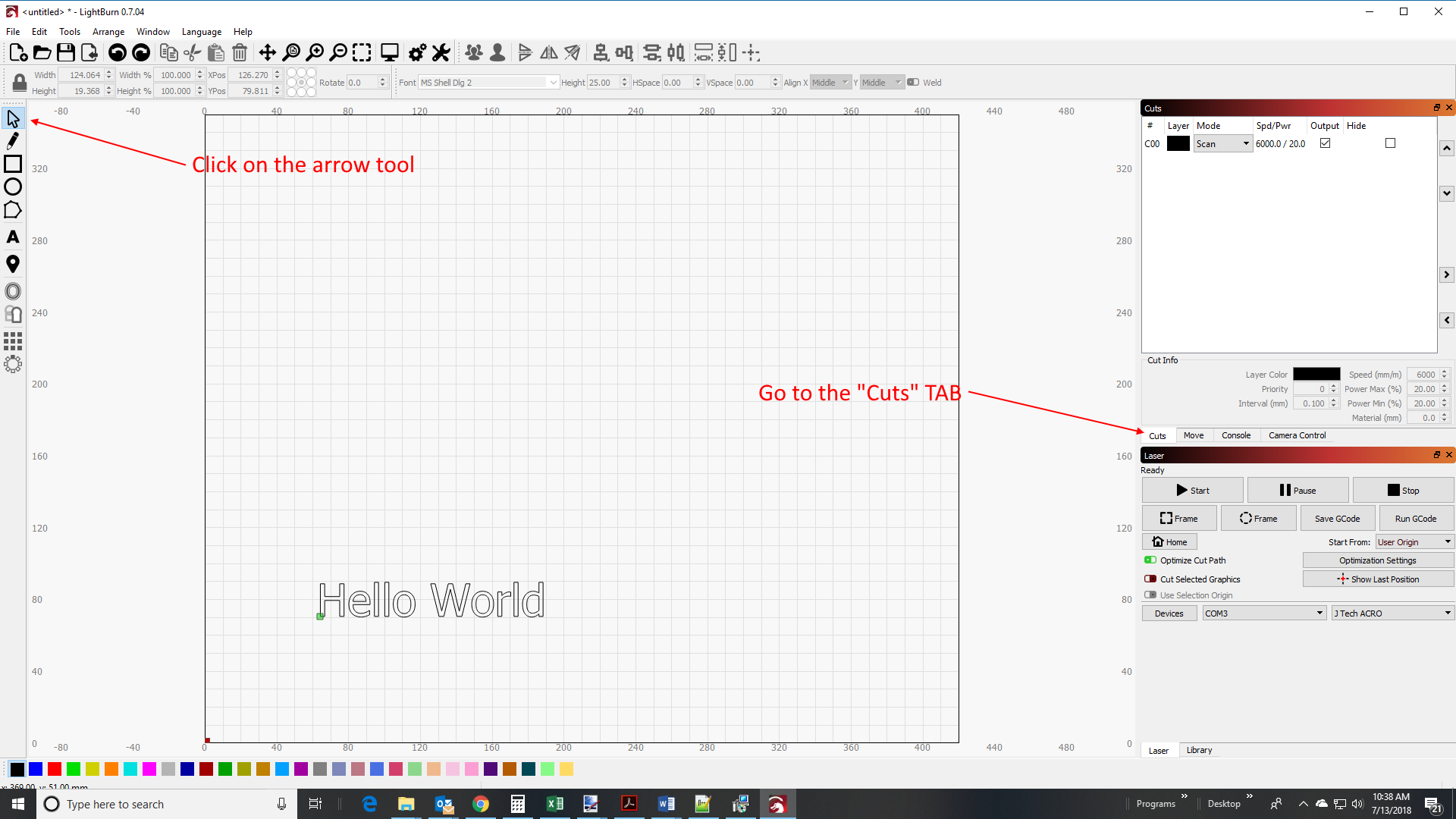
Change the Speed to 1500 and the power to 100%
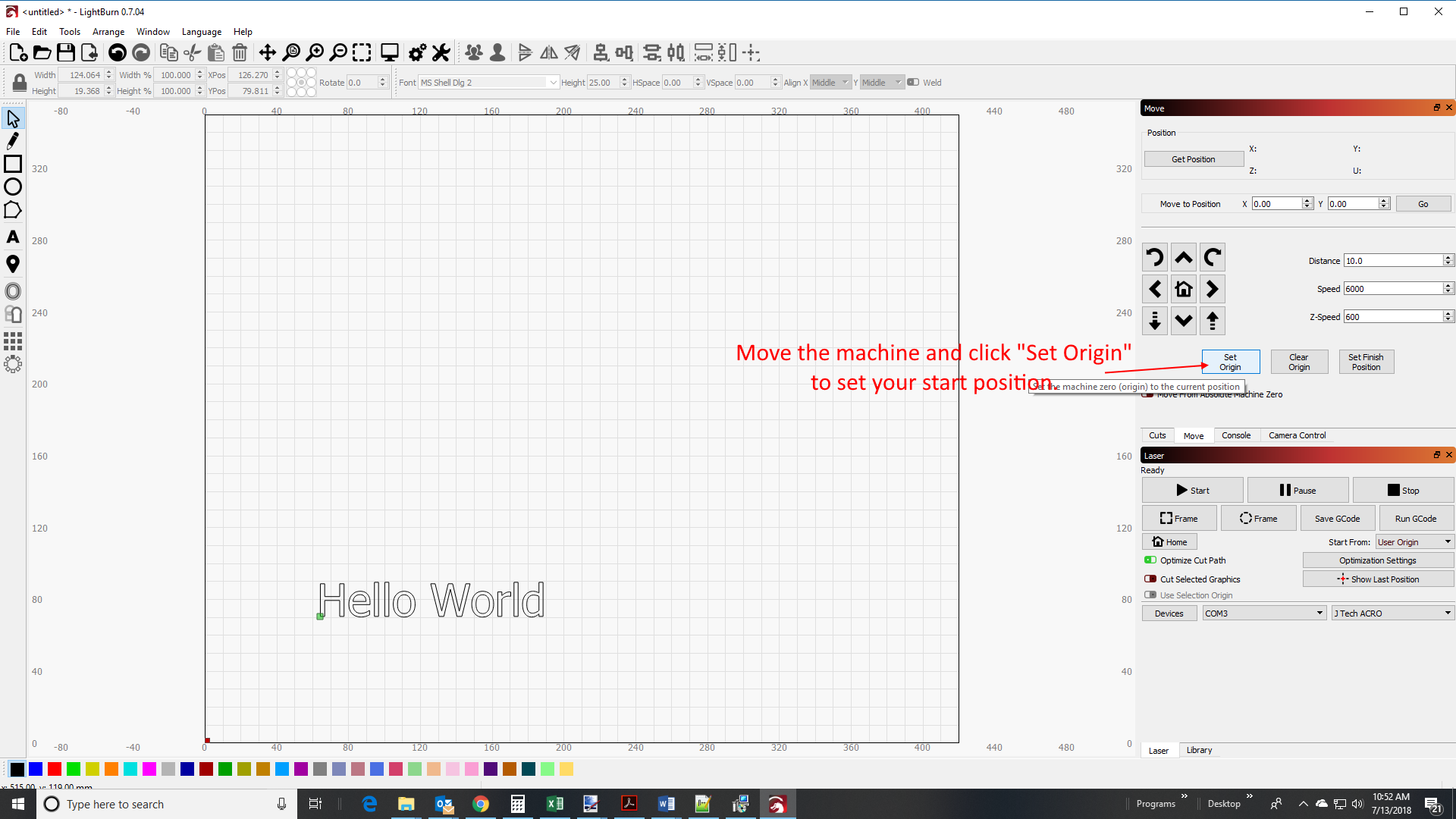
3. Set the Origin
In the move tab, jog the machine to your desired position to start the engrave. Click on “set origin”.
4. Run the machine
Set the start from box to user origin. You can also select “current position”. If you use absolute coordinates, you need to position the laser in the front corner of the machine.
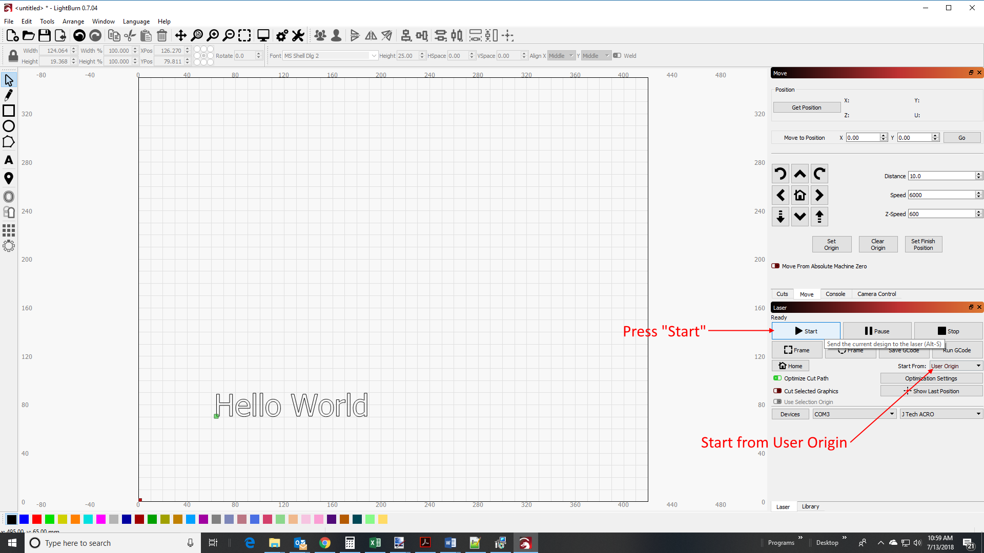
Your machine should start running and complete the engraving of the “Hello Word”. To learn how to do some more really cool things with your machine, follow the video tutorials in the next section.
Tutorials
These tutorials will walk you through the user interface and many of the features of lightburn software.
Tutorial #1: User interface and feature walk through
Tutorial #2: Cut settings
LightBurn Basics #1: Importing, selection, grouping, movement
LightBurn Basics #2: Text features and Offsetting
LightBurn Basics #3: Image Trace and Weld
Documentation
You can find the ligthburn documentation here: LightBurn Documentation
Other Software Options
There are a lot of software options for the machine. Here are some to choose from if you don’t want to use lightburn.
G Code Creation Software
- Vectric Laser Post Processor – If you have Vectric products, like Cut 2D, V Carve, or Aspire, then you can use it to create vector engravings with the laser. Here is the link on how to create g code using Vectric:
2. Inkscape Laser Plugin – This is a free pluging to use with the free Inkscape drawing program. It is a basic outline vector tool. The best part is it is free, but it has limitations. Learn how to use it here:
G Code Sender Programs
- Universal G Code Sender – This is a free sender program to talk to your machine. It will send your G Code to the machine and you can jog and communicate with it. You will still need to use another program to make your g code.
Old Electronics Bundle Instructions (Legacy)
Old Instructions for ACRO electronics bundle:
Main Electronics Board Assembly
This section will detail how to assemble the main electronics board.

Parts needed: GRBL Controller Board

Mounting Hardware Pack

Acrylic Mounting Board
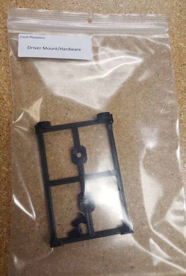

Driver Mount
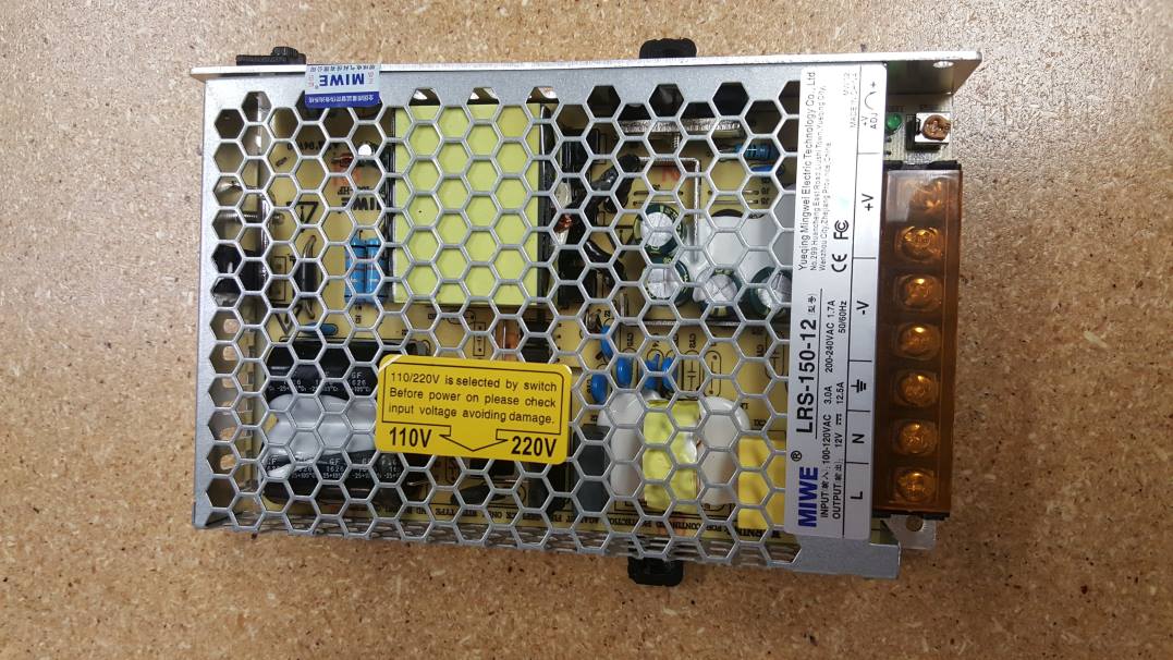
Power Supply
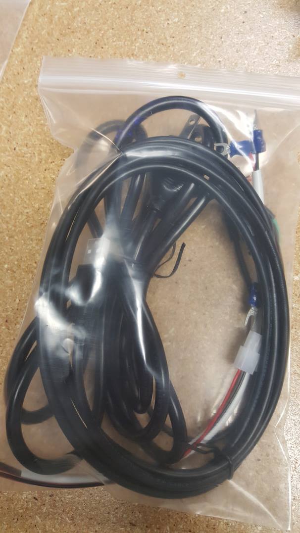
Cables
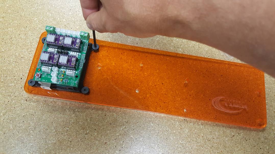
STEP 1: Attach GRBL Controller
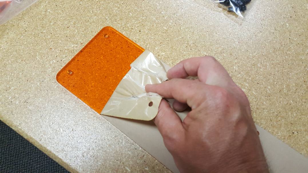
Peel off the paper on the plastic.
Screw in the GRBL controller the the plastic board as shown using the M5 screws and nuts.
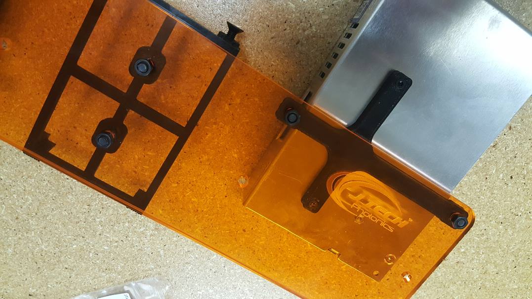
STEP 2: Attach Driver Mount

Screw in driver mount as shown in the picture below. Use the M5 screws in the mounting kit hardware pack.

Put two screws in the side for the driver holder.
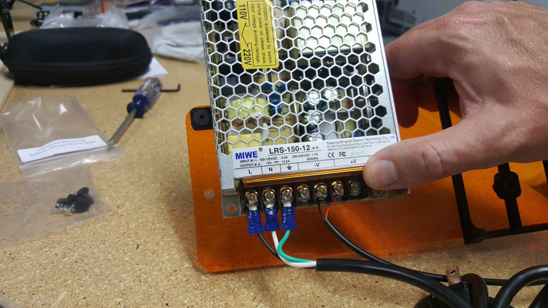
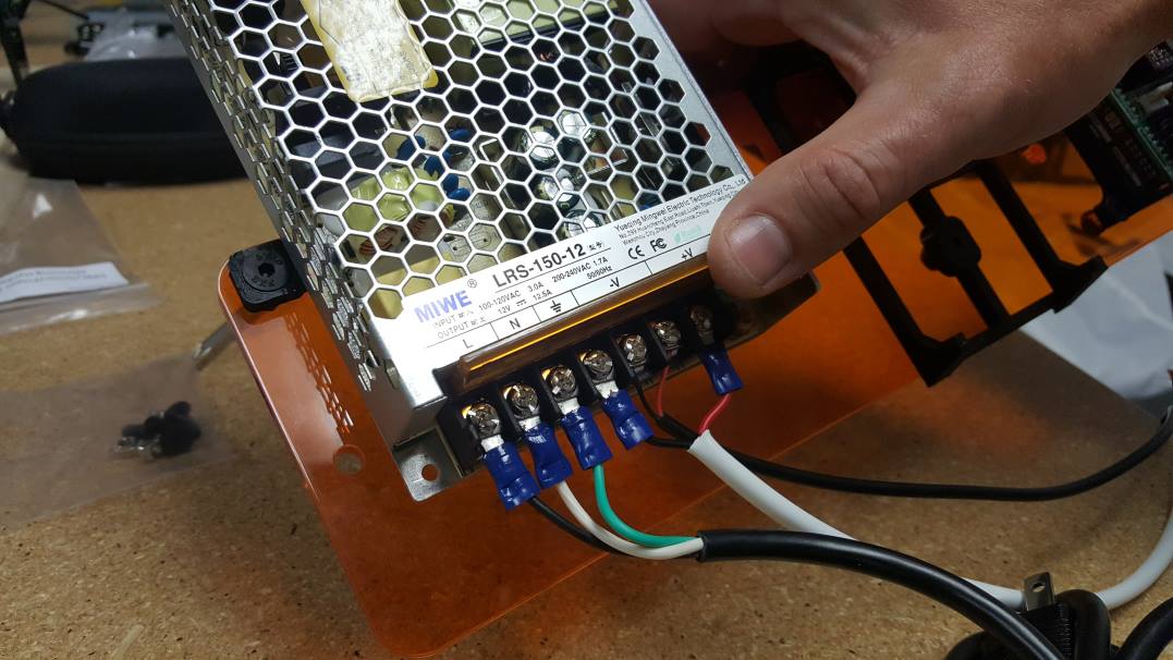
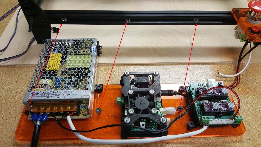
STEP 3: Attach Power Supply
The power supply will come with a mount piece already attached like the picture below.
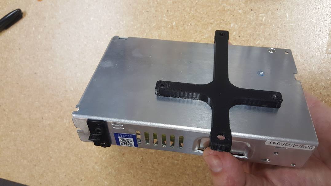
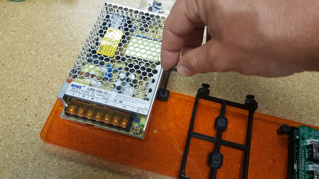
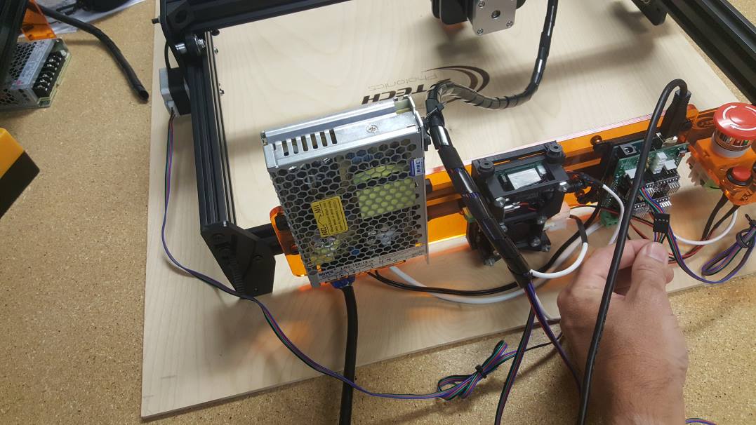
Mount the power supply as shown below:
STEP 3: Wire AC power Cord
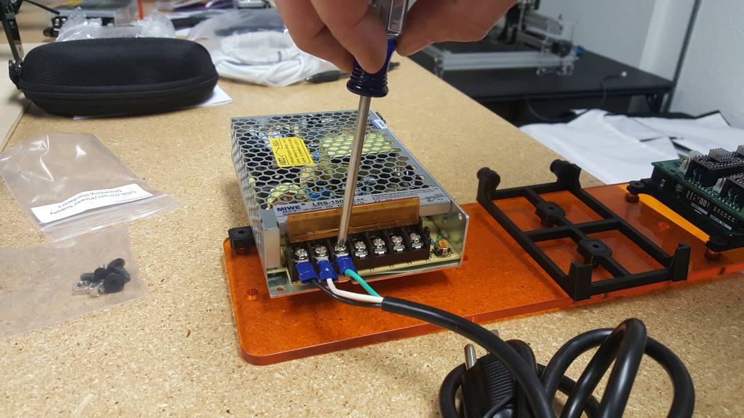
Take the AC power cord and connect the wires as shown in the picture below.
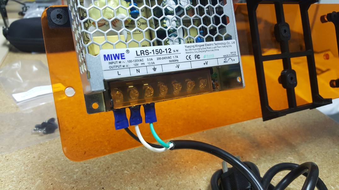
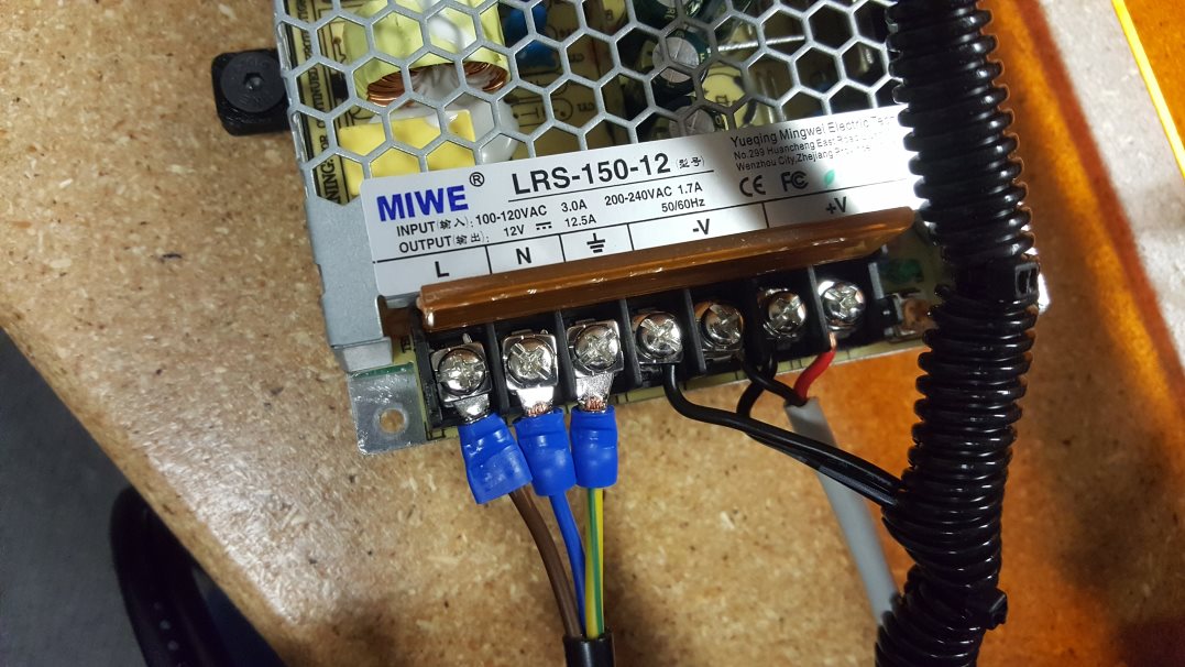
***If you are in the EU, the cord will be different than in the US. Here is a picture of the EU style cord (click for bigger picture):
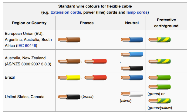
Here is a handy diagram for the other areas in the world for power connection colors:
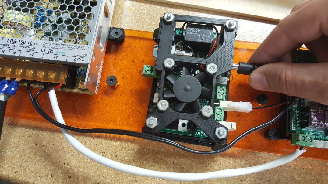
STEP 4: Attach Laser Driver Power Cord
Attach the bullet laser driver power cord. It will be in the cable bag and have a bullet connector on one end and a red and black wire on the other. Put the Red wire to V+ and the Black Wire to V- on the power supply.
STEP 5: Attach GRBL Controller Power Cable
Screw in the White GRBL power cable from the cables bag. Red Wire to V+ on the power supply and the Black Wire to V- on the power supply.
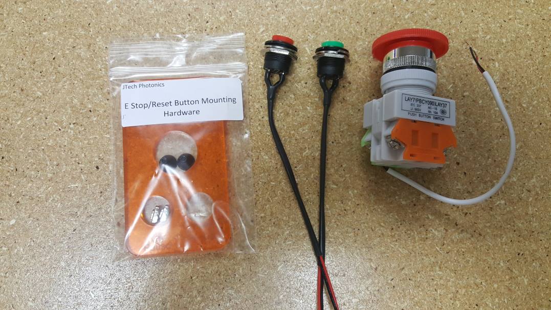
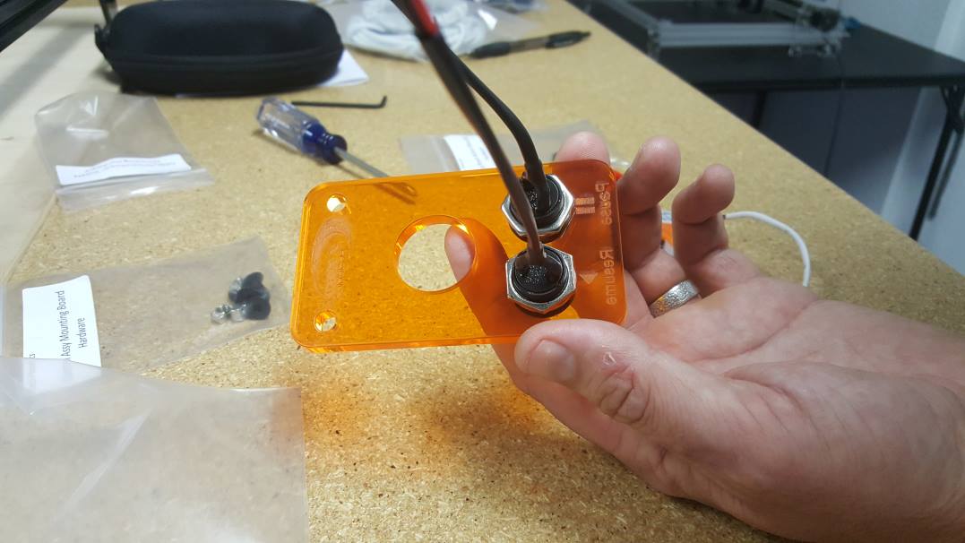
E Stop / Pause / Resume Board
In this section, we will put together the pause/resume/ E stop board.
Items Needed:
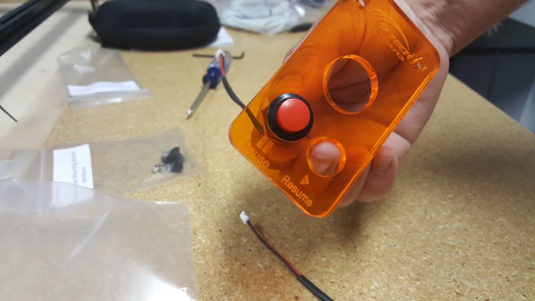
STEP 6: Pause Button
Insert and screw in the RED pause button into the plastic board.
STEP 6: Resume Button
Put the GREEN Resume button into the other hole.
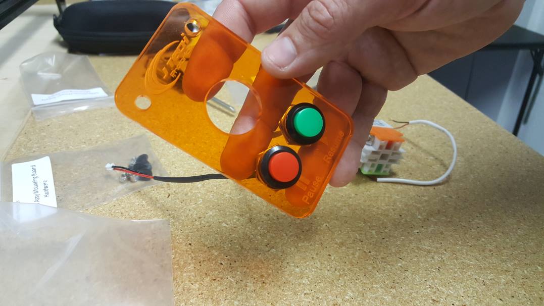
Make sure they screw in all the way on the back.
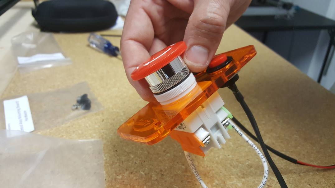
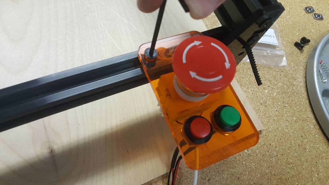
STEP 7: E Stop Button
Take the top of the E Stop button off the main body assembly.
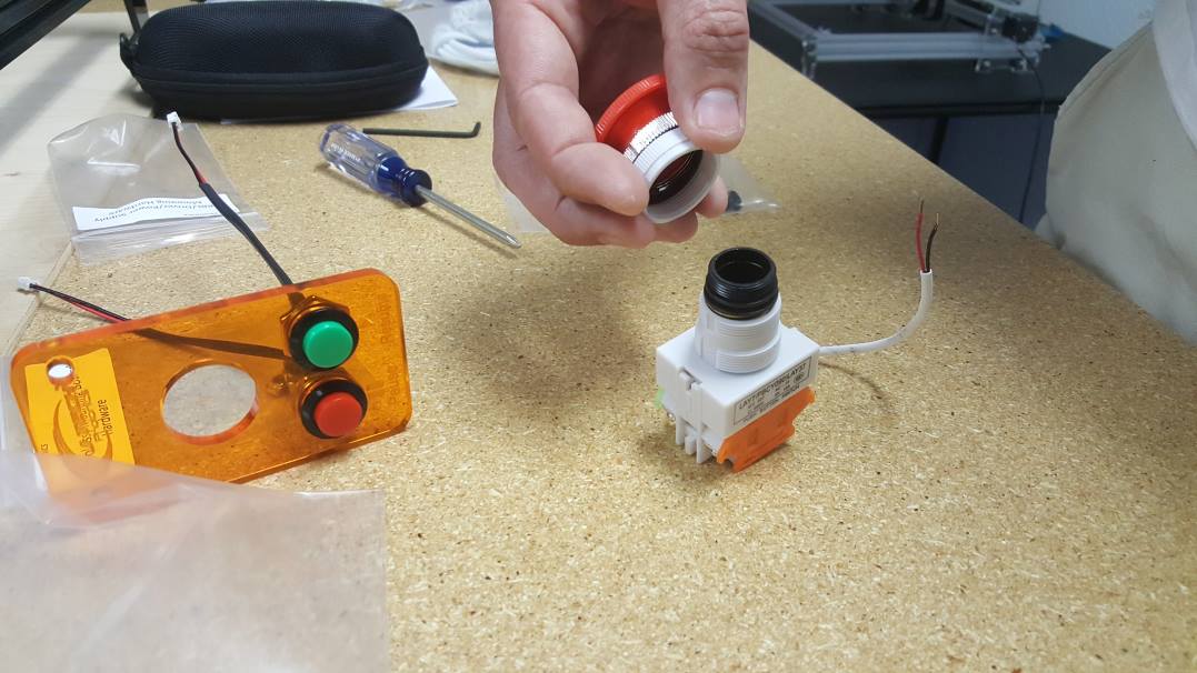
Insert the bottom through the plastic board and place the top on. Screw the top portion onto the bottom again. It should be able to push down and then turn to pop back up.
STEP 9: Install Driver
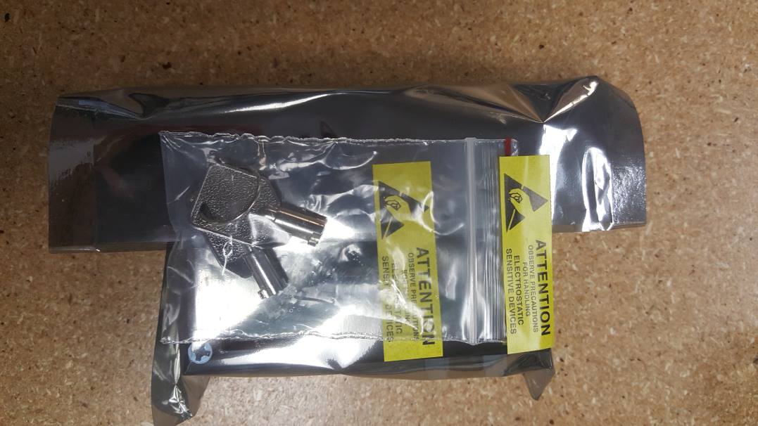
Driver in the bag
Put the driver in the back panel and tighten the holding screws down.
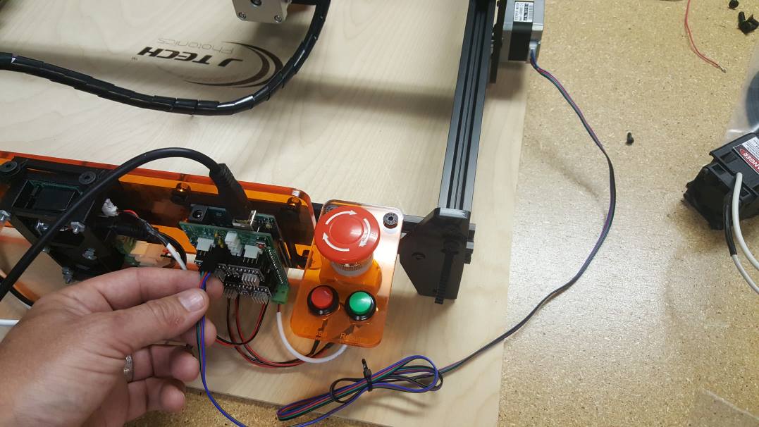
STEP 10: Install E Stop Panel on Machine
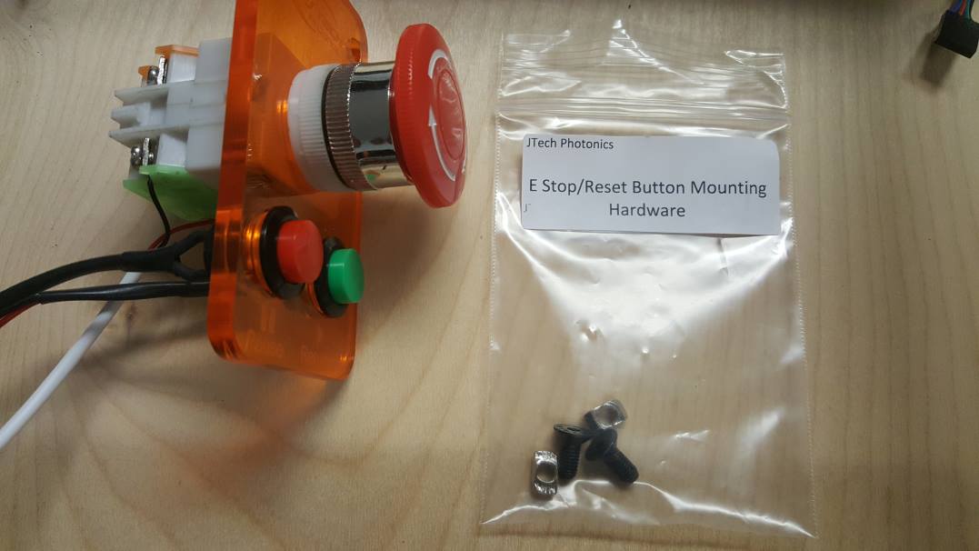
E Stop Panel and Bag of Hardware
Take the two drop in V Slot nuts and position them in back right corner of the machine. Line up the holes with the nuts and put them into the slot.
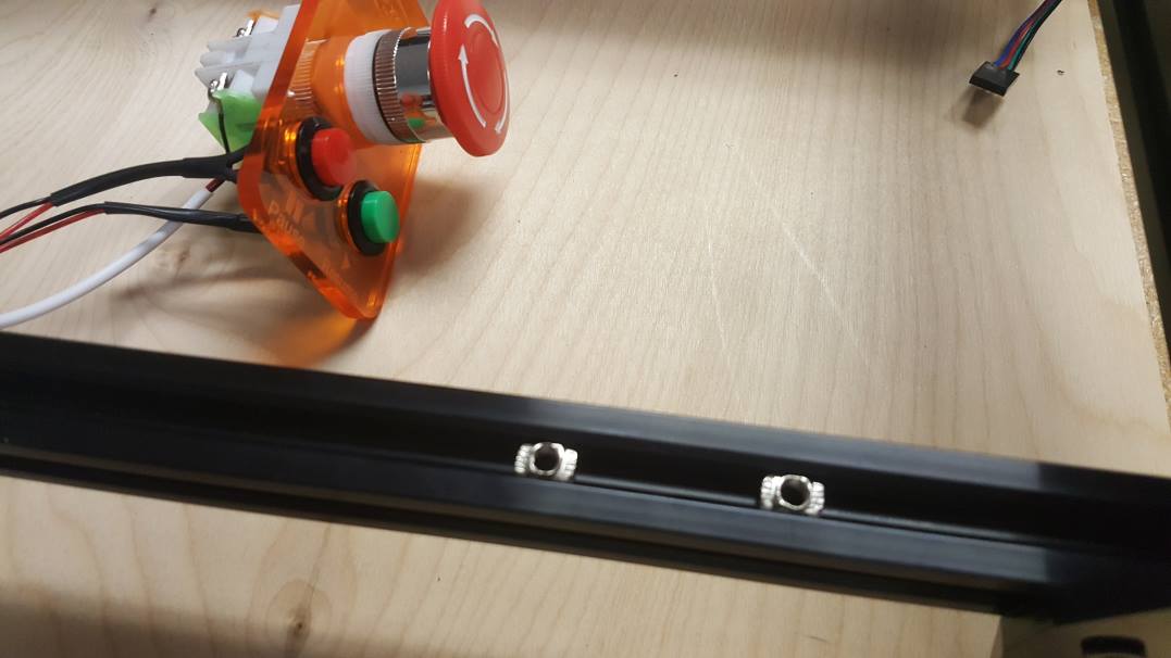
Line up the hole and put in the M5 screw from the hardware pack into the V slot nut. Do not tighten fully yet.
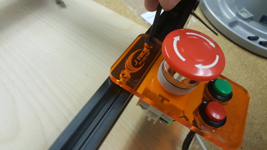
Put the other M5 screw into the other V Slot nut. Move the plate all the way to the right and lock down both nuts.
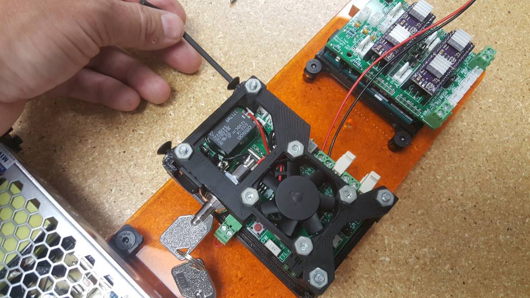
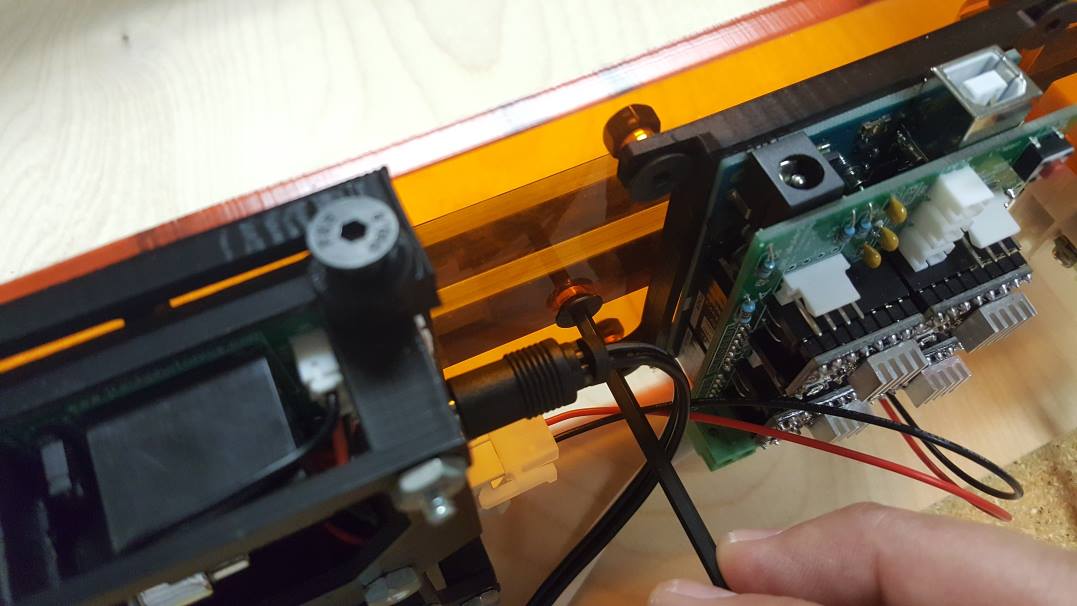
STEP 11: Wire Controller Back Plate
Connect the PWM wire from the laser driver to the GRBL controller. Put it in the spot labeled “PWM”.

Screw in the white power cable from the power supply to the GRBL power input screw terminal on the left side of the board. Make sure to get the RED wire on the positive side and the BLACK wire on the negative.
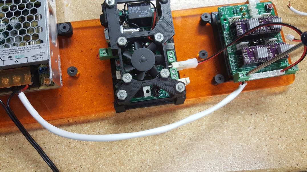
Plug in the bullet power cable to the laser driver power input.
STEP 12: Put the Back Control Electronics Plate on the Machine
First, line up the back plate to the back right of the machine. Put the V Slot drop in nuts in line with the holes. Put them in the slots like in the picture below.
Pick up the back plate and align to the nuts in the V Slot. Screw in the first screw to the nut, but do not tighten all the way. The next screw, move the plate so you can line it up and tighten it slightly. Do the same for the third screw. Now, slide the plate to the right and tighten all of the screws.
STEP 13: Attach Z Stage (*if you didn’t order the magnet Z Stage, then skip)

Parts needed: Z Stage and Screws
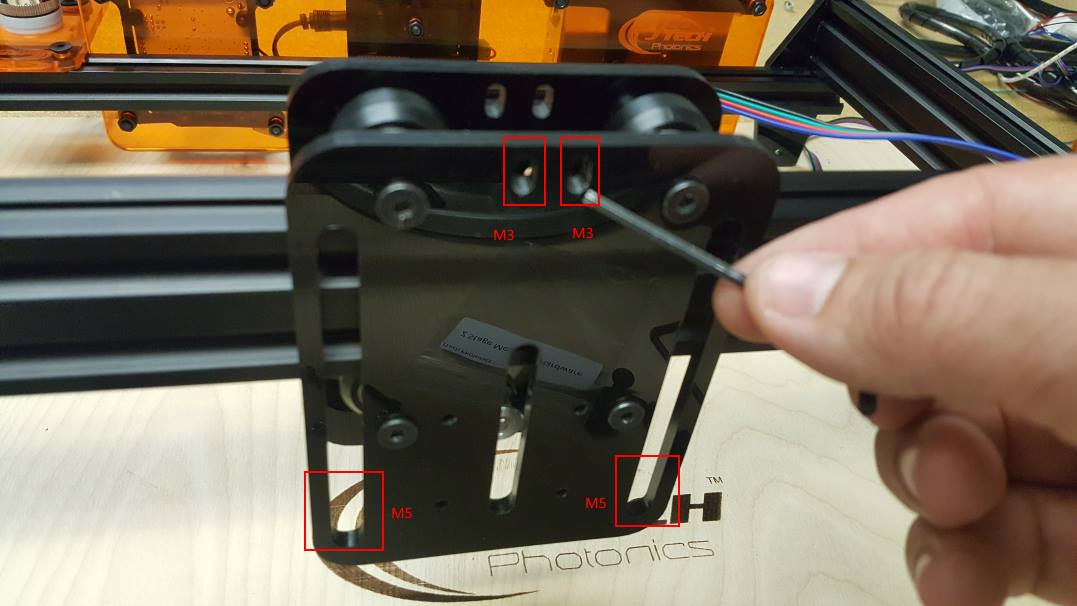
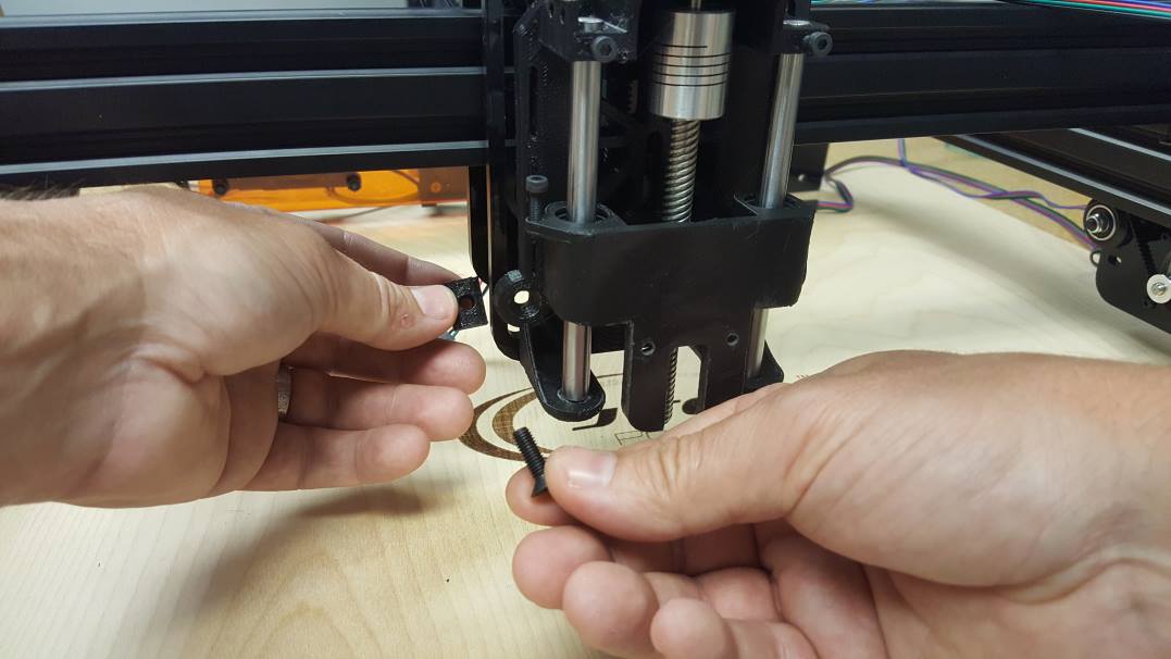
On the ACRO laser mount plate, locate the holes for the screws to mount the Z Stage. Two M3 screw holes are at the top. The M5 screws will go in the side rails.
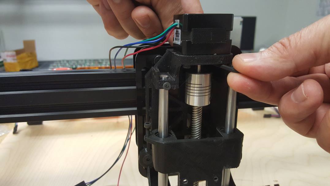
Put in the M3 Screws just under the motor on each side of the shaft.You can see the M3 screws in the picture below.
Place the Z Stage onto the ACRO plate and line up the M3 screws through it. Put the nut onto the M3 screw.
Do this for both screws. Do not tighten the nuts all of the way to allow for the M5 screws to be aligned.
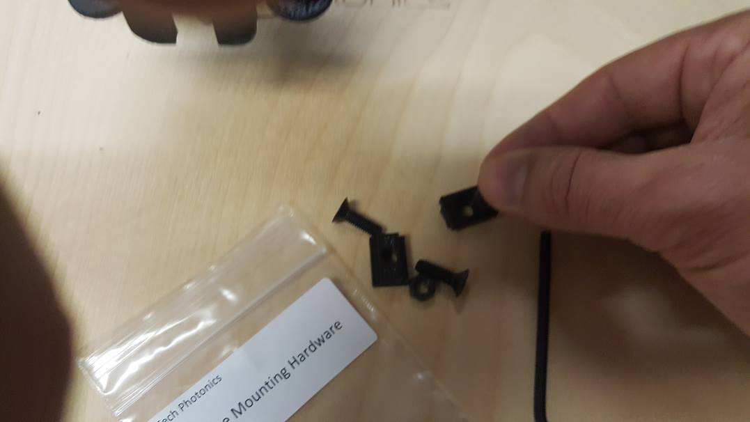
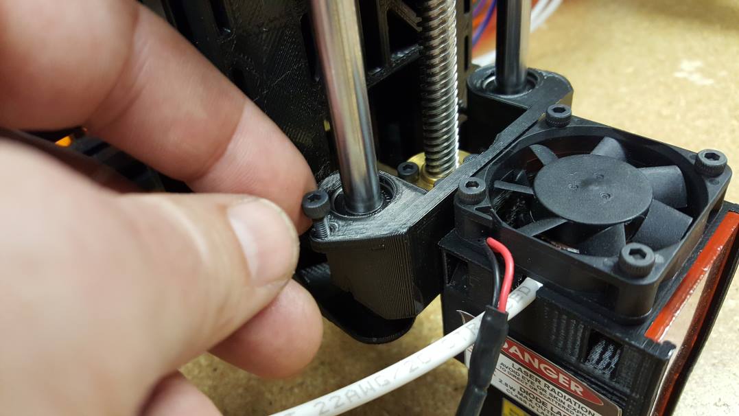
Take the M5 screws, nuts, and plastic nut holders out of the hardware bag.
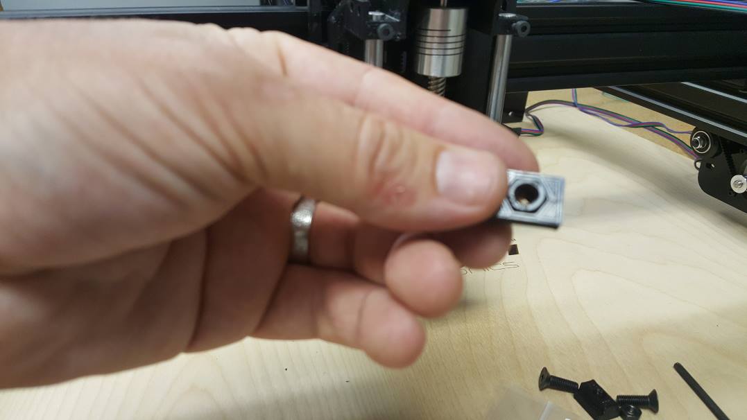
Put the M5 nut in the plastic holder.
Screw in the M5 screw into the plastic holder with the M5 nut.
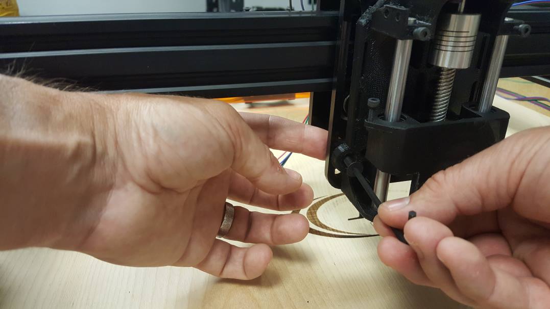
Tighten the screw, but not all the way.
Repeat this for the other side as well.
Now that all of the screws are in, tighten both M3 screws and the M5 screws.
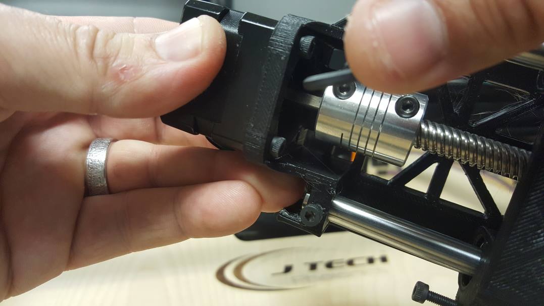
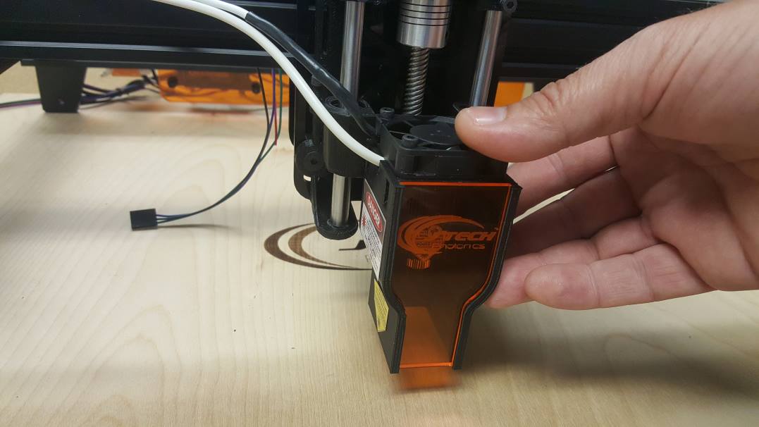
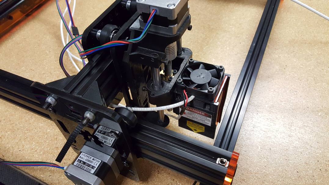
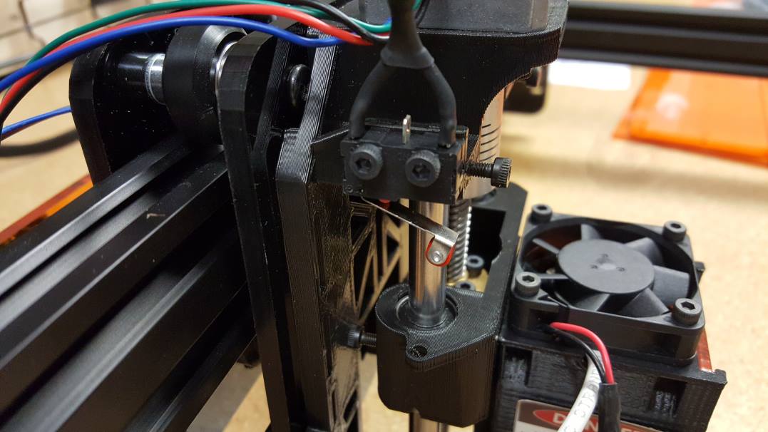
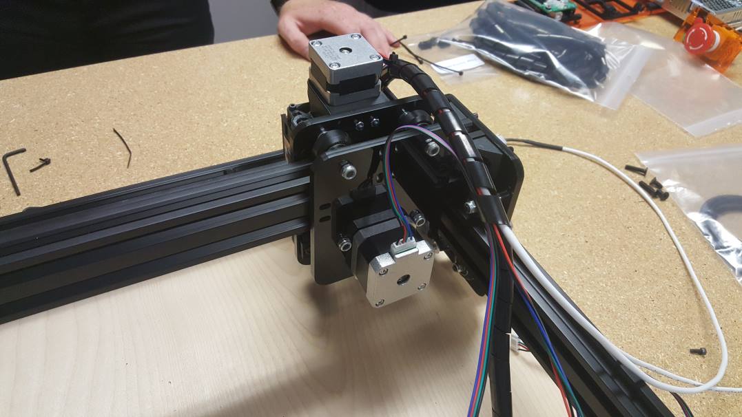
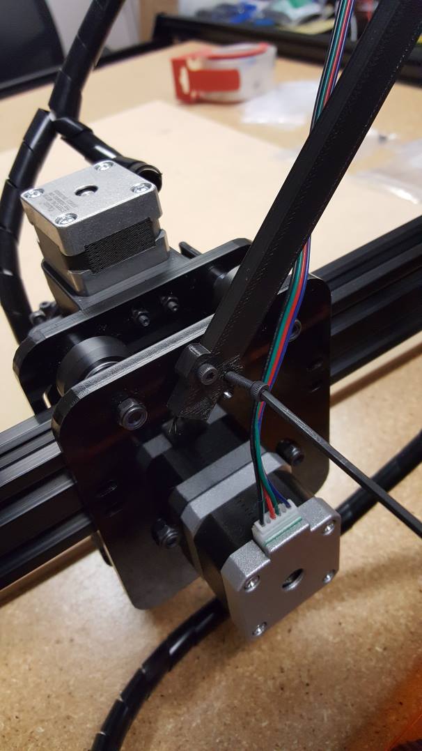
Unwrap the laser and position it with the two alignment holes on the z stage.
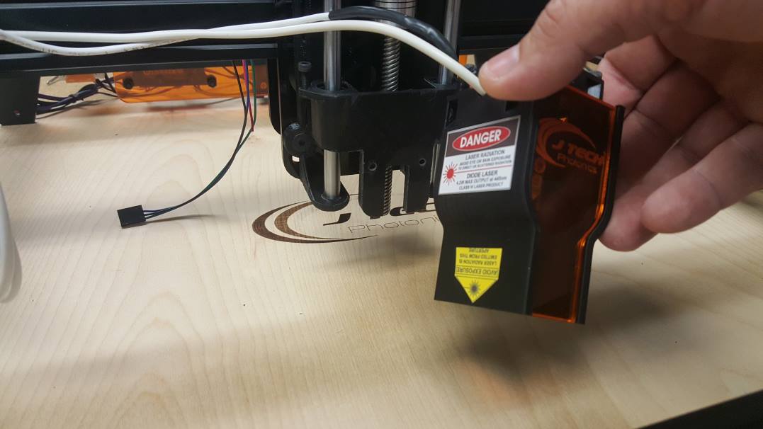
Fully seat the laser on the Z Stage so that the two screws fit in the alignment hole and the back is flush with the mount.
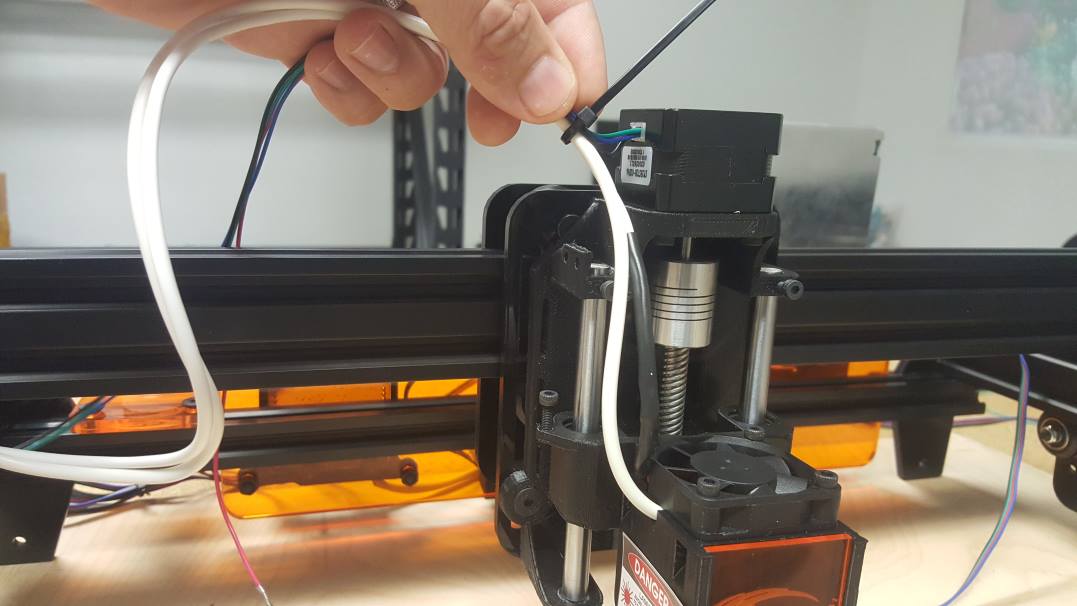
Zip tie the Z motor cable, Laser cable, and the fan cable together at the motor.
STEP 14: Wire E Stop / Pause / Resume to Controller
Attach the E Stop wire to the Controller on the right screw terminal.
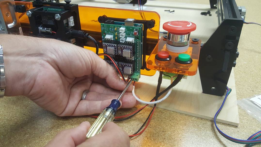

Plug in the Pause button into the far left JST connector on the GRBL Controller.
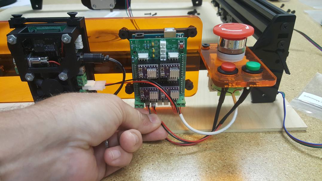
Plug in the Resume button in the JST connector to the right of the Pause button as in the picture.
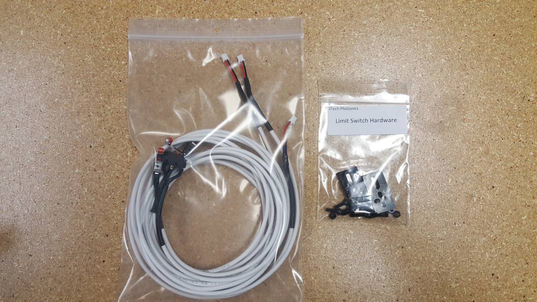
STEP 15: Limit Switches
You don’t necessarily need limit switches to do engraving with your ACRO laser system, but sometimes they might be nice to have. Here is how to install them. You will need to bag of limit switches with the cables and the limit switch hardware.
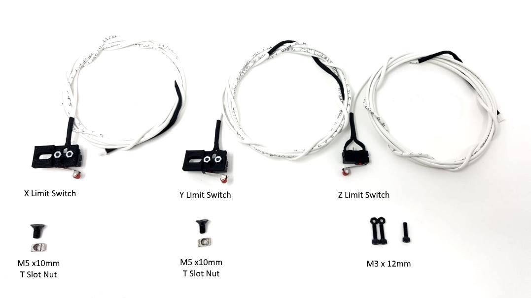
X and Y Limit Switch Assembly – Put the switch on with the the limit switch for the X and Y axis should look like this:

Move the Machine to the Front Left Corner. This will be the 0,0 of your machine.
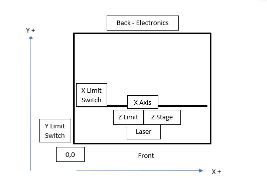
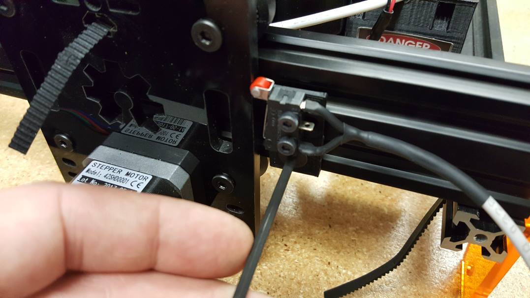
Install the Y Axis Limit switch.
Put the M5 screw with the T Slot Nut into the bottom T Slot. Position it so the switch just engages onto the plastic motor carriage. Tighten it down to keep it in place.
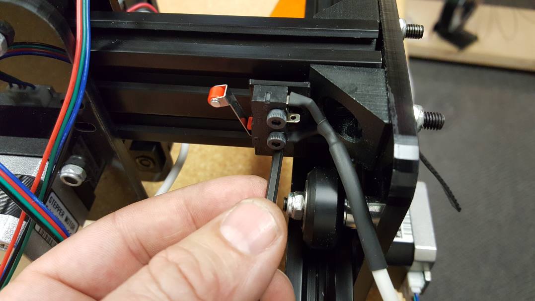
Install X Axis Limit Switch
Do the same for the X axis. Push the switch all the way over to the side to make sure you maximize your travel. Lock it down on the t slot when in place.
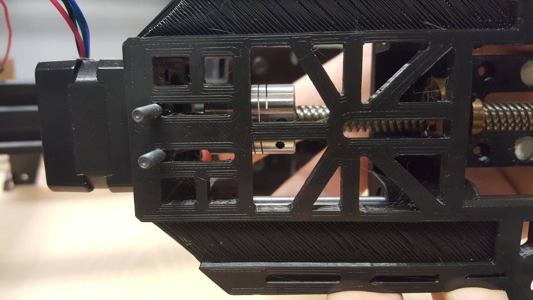
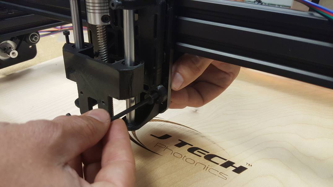
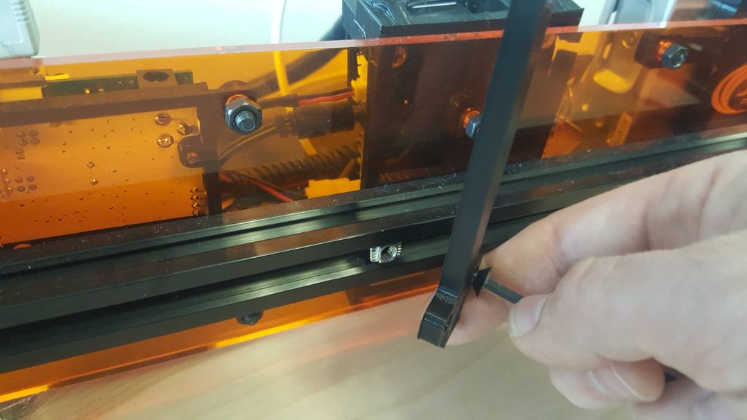
Install Z Axis Stop Screw
Use the M3 12mm screw to put it in the Z Axis slider to push on the limit switch. You can adjust this to maximize your z travel when completed.
Install Z Axis Limit Switch on the Z Stage
There are two small holes for the limit switch to fit into. Place the M3 nut in place with your finger and feed the M3 screw through the limit switch. Tighten it and do the same for the second screw and nut. Tighten it fully when you get both screws in.
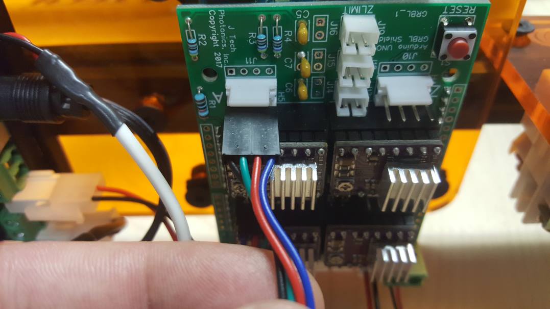
Install Limit Wires to GRBL Board
X Limit Switch:
Y Limit Switch:
Z Limit Switch:
STEP 15: Final Wiring
In this step, we will wire the motors and connect the Z Stage cables including the motor, laser, and fan.
Depending on the size of your machine, you will need some or all of the motor extension cables. We will also be wrapping the Z Stage cables in this step.
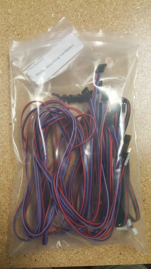
Extension Cables
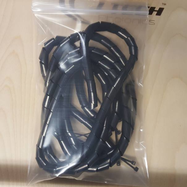
Wire Wrap
Attach the motor extension cable to the Z Stage. Do this for any of the motors that the cables don’t reach to the back of the control board.
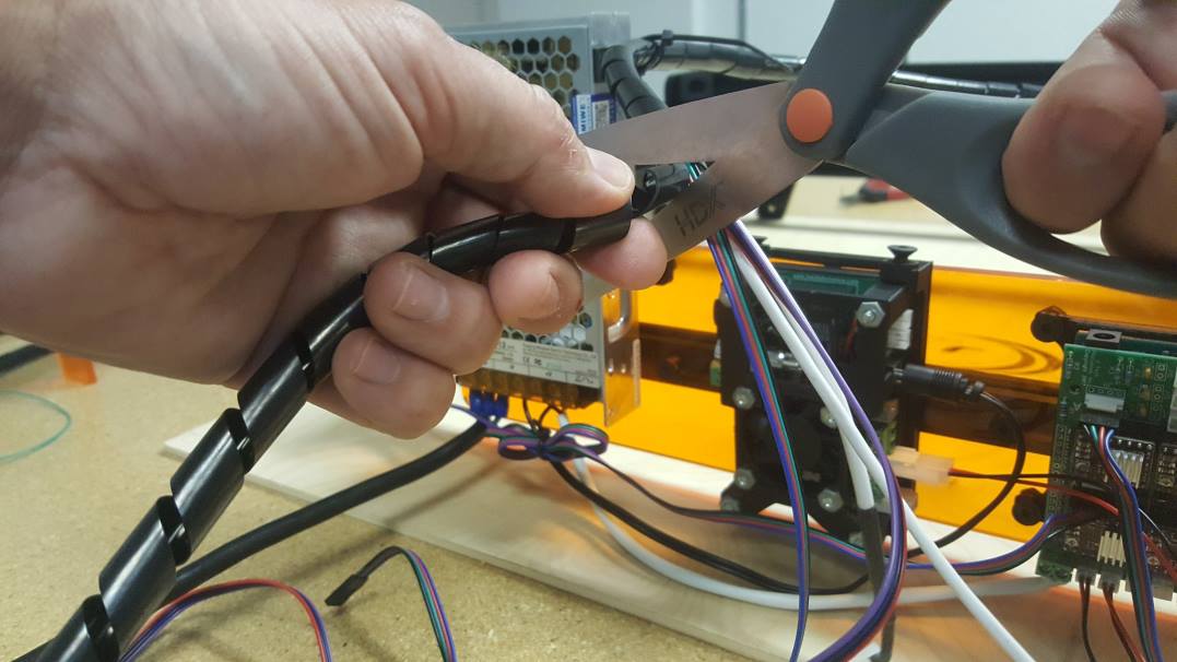
Measure out the wire wrap to the laser.
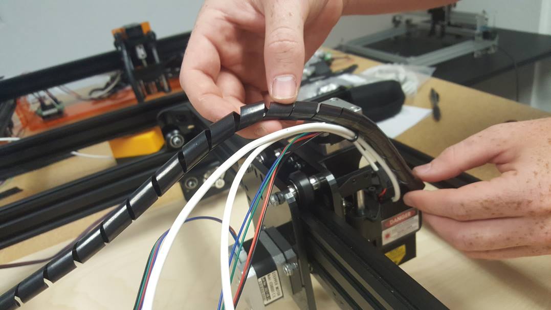

Rotate the wire wrap over the cables to put it on.
Wrap down to the laser and continue by placing the X Motor cable in the wrap.
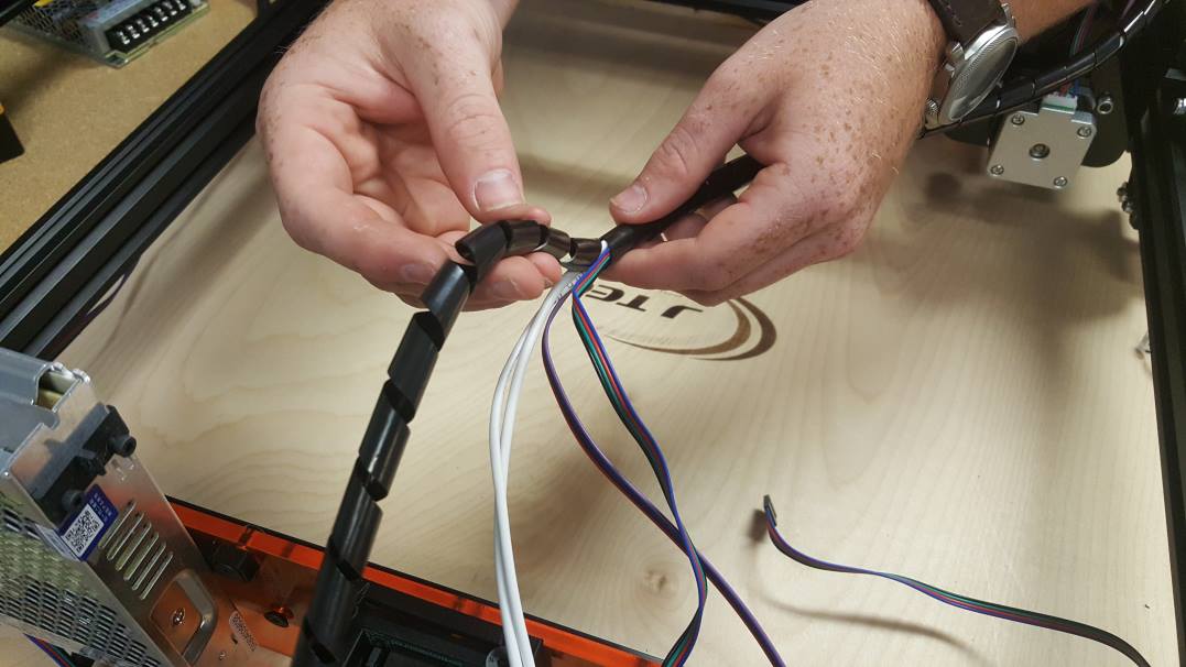
Keep wrapping…
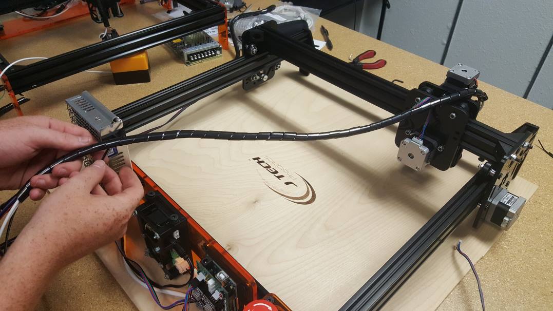
Make sure the Y stage and X stage are pushed as far away from the controller as possible in the front right corner of the machine. This will allow you to wrap the correct amount of cable for the machine. Pull it towards the power supply so there is no slack.
On the power supply, zip tie the wrap to the zip tie holder.
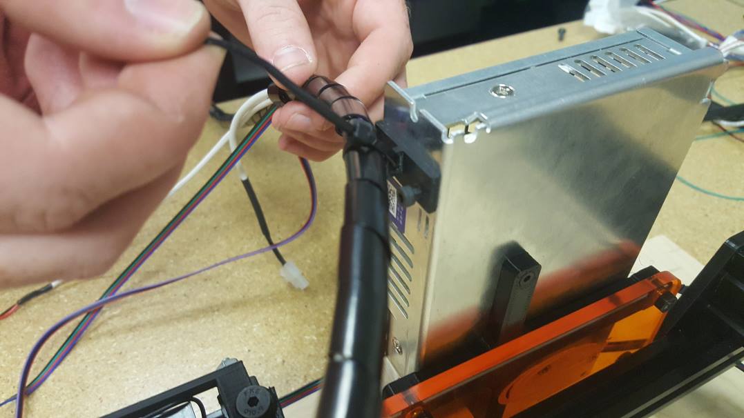
Cut any excess wrap material off.
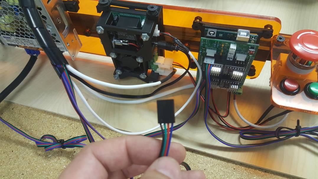
Attach the laser fan to the laser driver board in the JST connector shown.
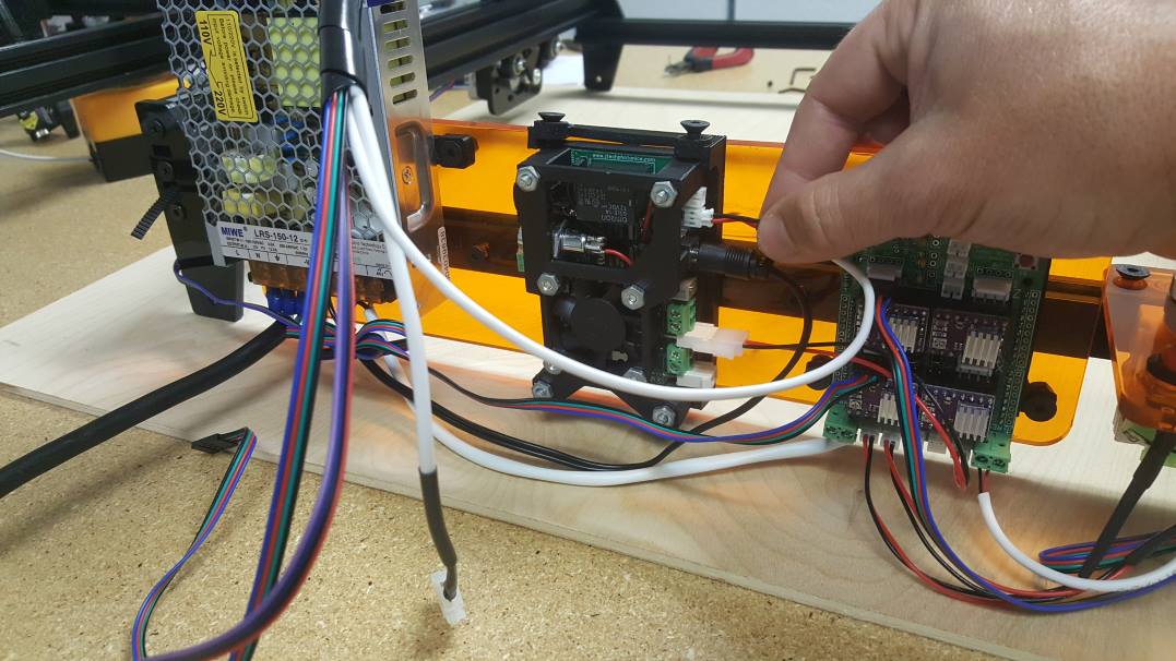

Connect the laser mini fit jr cable to the bottom connector on the laser driver board.
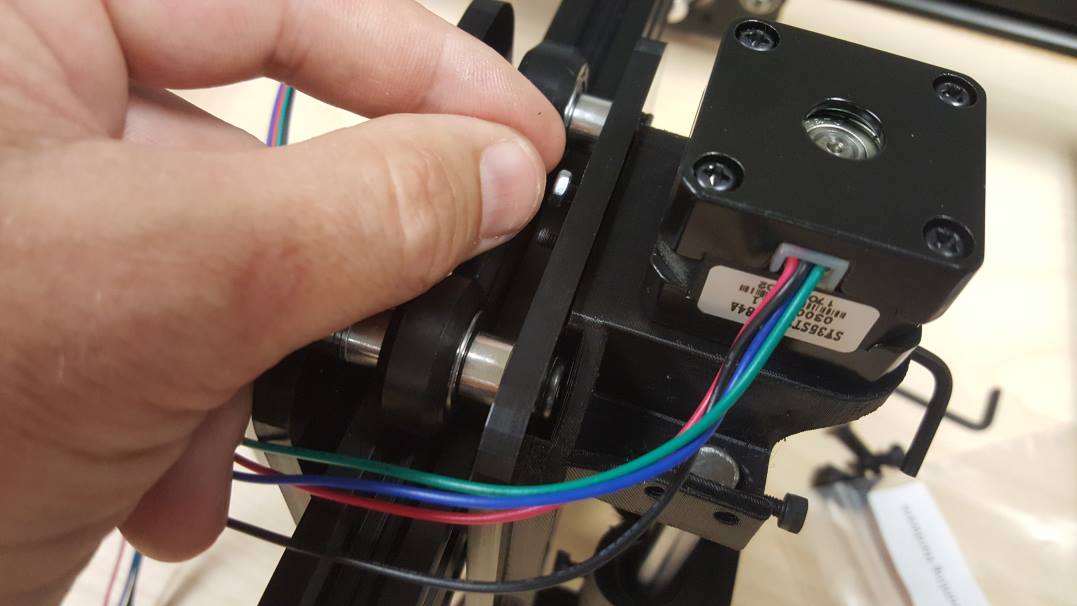
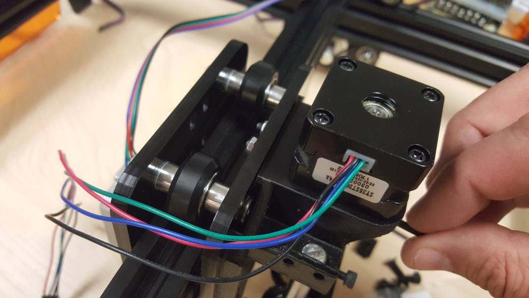
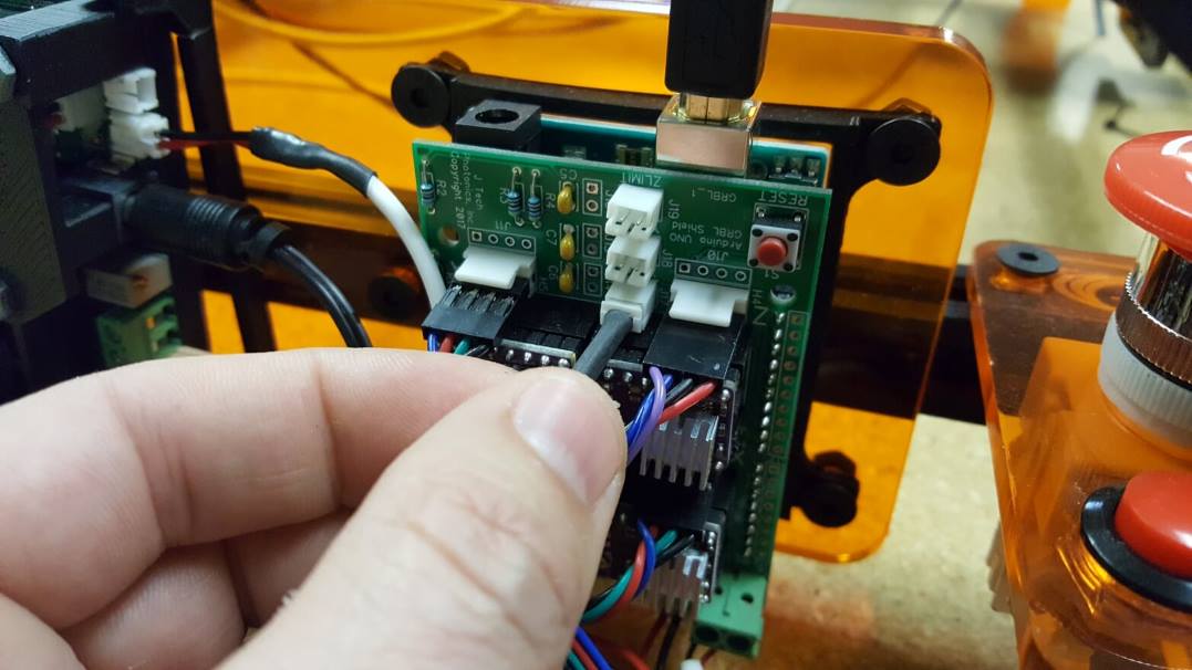
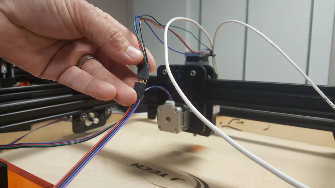
Prepare to connect the Y axis motor to the GRBL controller. It will be the “A” axis. In some cases on the larger machines, you will have an extension cable here.
Connect it to the A axis motor connection on the GRBL controller.
Do the same for the other side of the Y Axis.
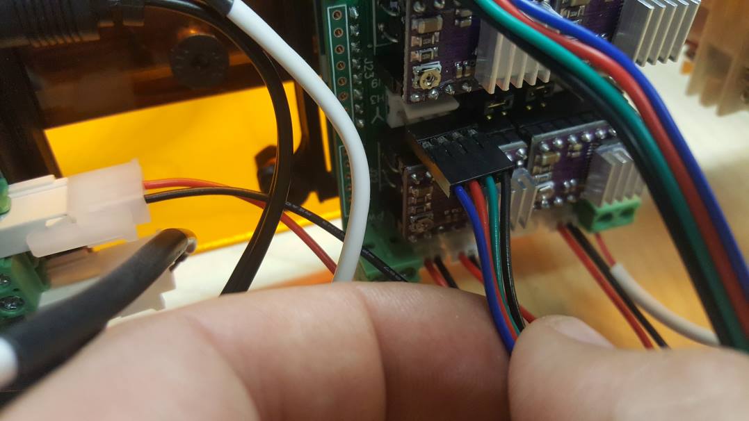
Plug it into the Y axis motor connector on the GRBL board. Notice this cable is placed backwards compared to the A axis.
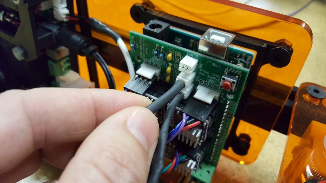
Locate the X Motor cable from the wrap and prepare to put it on the GRBL controller.
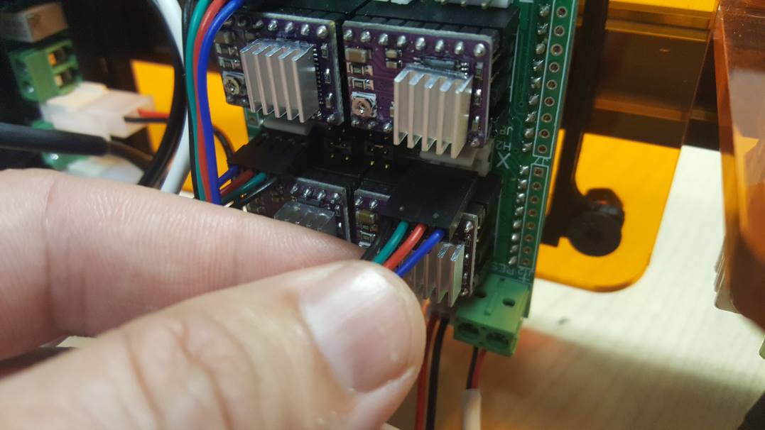
Put the cable in the X motor connection on the controller board.
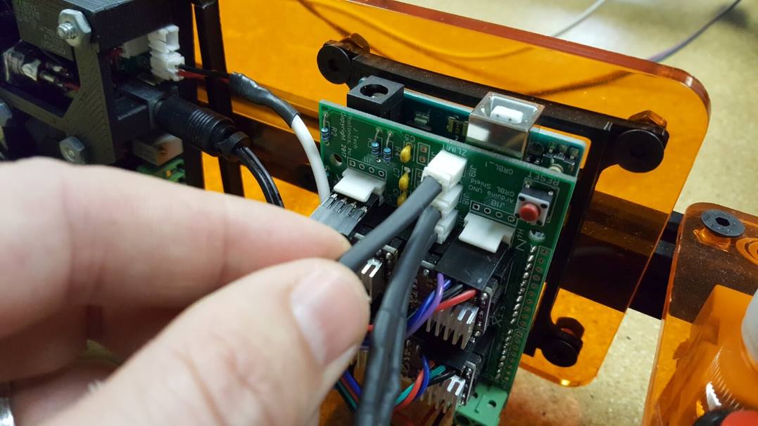
Do the same for the Z motor.
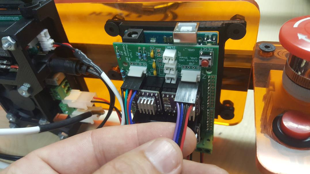
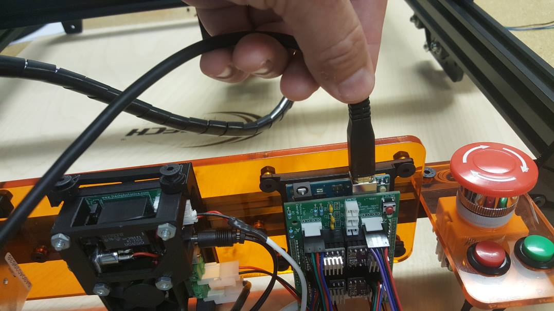
Connect the USB cable to the controller as the final step.
Cable Post Holders (for larger machines)
The kit includes two cable holders to prop the cable from the X and Z axis up so the machine does not run it over. This may not be needed if you have the 20″ x 20″ machine, but it is a good idea for the 40″ x 40″ machine.
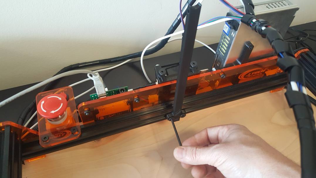
You can attach the back holder using two t nuts and two M5 x 12mm screws.
On the back side of the Z Gantry, put the smaller holed cable holder on the back screw holes using the M3 x 16mm screws and nuts. We angled ours slightly sideways to push the cable away from the X carriage so the cable does not hit.
Final Wire Check:
Wiring Diagram:
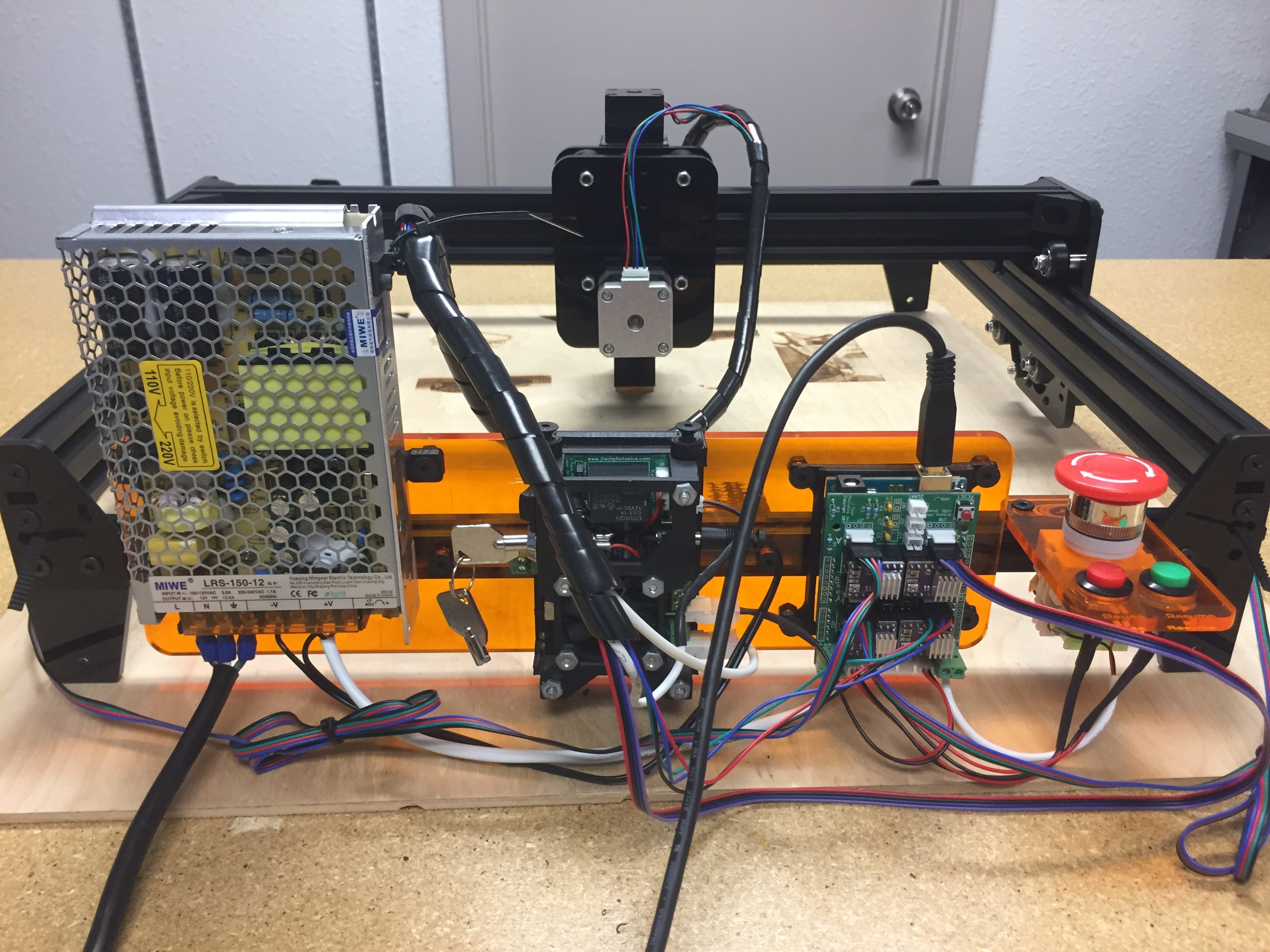


Finished!!! Next, we will look at how to run the new machine.