


*Disclaimer*
All instructions for upgrading machines are all done at the buyers or viewers own risk. Lasers are inherently dangerous and all safety measures are the responsibility of the buyer or viewer. While we provide some safety features on our laser kits, it is not a complete laser machine, so all additional features are up to you when you build your machine including interlocks, fume extraction, and fire prevention. Any company or machine mentioned in this webpage is not associated with J Tech Photonics Inc. and they in no way endorse these instructions.
Moving onto the instructions…
This machine is the new upgrade for the very successful Shapeoko product. Keeping up with their success with the Shapeoko, they have made some improvements to the entire system, making this a very powerful CNC for hobbyists and industry alike.
We have sold many kits for this machine and decided it is time for us to get one in the lab to tinker with and show everyone how easy it is to laser upgrade!
There are now three machine configurations offered, the 1000mm large version, 750 medium version, and the 500mm version. We opted for the 1000mm kit and have made some cool parts to make the upgrade seamless. We did ours in under 1 hour and were laser engraving test pieces that turned out perfect! We have instructions here on how to complete the full build and are also offering the mouting Kit for sale in our shop that includes all of the printed pieces and mounting hardware.
*Update 10-5-2016* New Model Changes
The instructions here have been updated to reflect changes with the new machine. The only difference is the electrical portion with the addition of the new Controller and the lack of the terminal block in the back of the gantry. We have modified our mounting kit with a longer 11′ cable for the laser control.
In order to complete the following instructions, you need to purchase the mounting kit from our shop. The laser kit alone does not have the components needed to complete the upgrade.
Purchase Mounting Kit HERE

Mike Merzke at Merzke Custom Woodworking has made a great video showing his installation of the laser kit to his machine. View it here to see how easy it is to upgrade.
Now that you have seen how easy it is, let’s get started!
Mechanical
We have given all of the mount pieces here in case you want to complete the upgrade on your own. However, we sell the complete mounting kit in our shop. The laser kit alone does not have the parts needed to complete the upgrade.
Purchase Mounting Kit HERE
If you want to print out your own parts, then here is the list of what you will need to get:
- 12’ Molex Mini fit Jr. Cable: https://jtechphotonics.com/?product=molex-mini-fit-jr-jumper-2-wire-connector
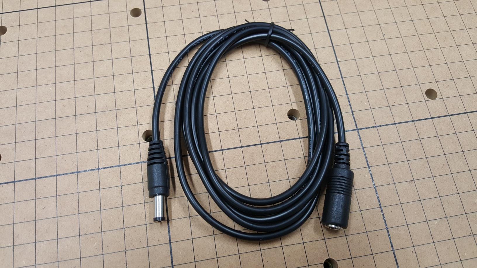
- Power Extension Cable: https://jtechphotonics.com/?product=power-extension-cable
- Quantity 4: 6-32 1 1/4″ screws and nuts.
- Quantity 2: M4 16mm screws and nuts.
Laser Mount
We have plenty of 3D printers in the lab cranking out parts 24/7, so we decided to design a quick mount for the laser utilizing them. The mount can either be placed in the hole where the router sits, or it can be placed on the side of the router so everything can stay on the machine. It is up to you which way to go. The mount can be used either way, just turn it over. If you want to remove your router you will get a little extra eye protection as the holder will block some of the laser light.

We decided to go with the “keep the router on” way of mounting it next to the router. We will show you pictures of how to put it together in the build section of the instructions.
Driver Mount
If you have the larger version (1000mm) you will need to place your driver on the gantry because the laser cable is not long enough. If you have the smaller version, then you can either leave your driver on the side of the machine or you can put it on the gantry, it is up to you! We designed this mount so it can be quickly released for when you are not using your laser. Sometimes it gets rather messy when you are using the router, so it is advisable to take the driver off the machine when carving.
The mount has two pieces:
- A bottom piece that will get bolted onto the Z motor.
- A top piece that gets bolted to the bottom that provides the base for the driver to “click” and lock into.
Here is the bottom:

DOWNLOAD THE BOTTOM DRIVER MOUNT
Here is the top:

Electrical
There are now two versions of the machine.
- Original Machines with the Arduino Uno – Shipped Pre-October 2016
- New Machine with X Controllers – Shipped after October 2016
We will cover the electrical instructions for both here in this section.
Original machine with Arduino Uno
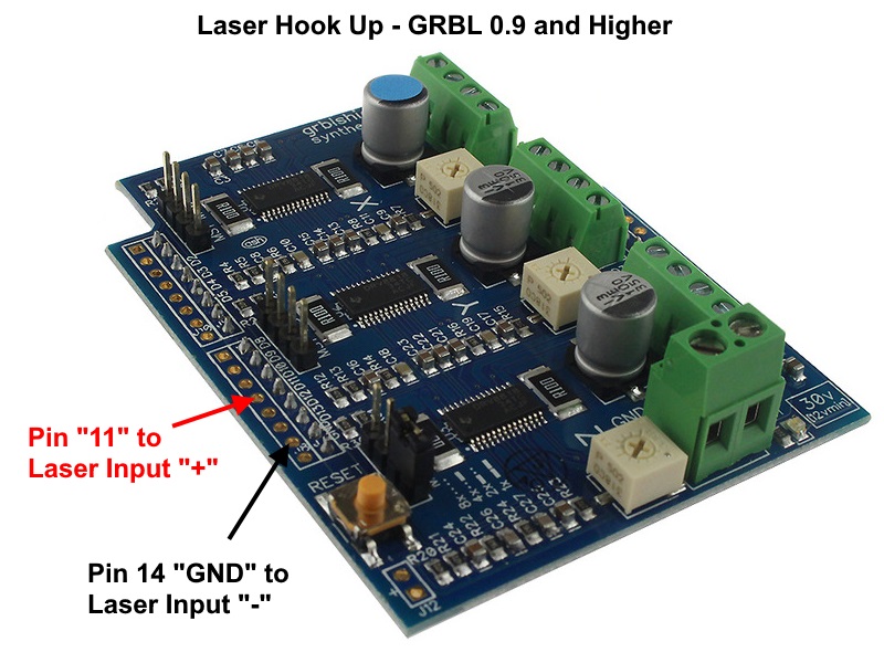
The machine uses the Arduino UNO and the G Shield electronics like on the Shapeoko 2. The Arduino that ships comes with a pre-installed version of GRBL 0.9j, which will work fine for most applications using the laser. We will need to hook up the output from the Arduino G Shield to the laser driver to provide the signal to turn it on and off. You will need to connect the following:
- Pin 11 Labeled “11” on either Arduino or GShield to Laser Driver Input “+”
- Pin 14 Labeled “GND” on either Arduino or GShield to Laser Driver Input “-“
The machine already has these cable connected for the spindle control for the 24V spindle. The wire for the Laser “+” is YELLOW and the Laser “-” is the BLACK wire.
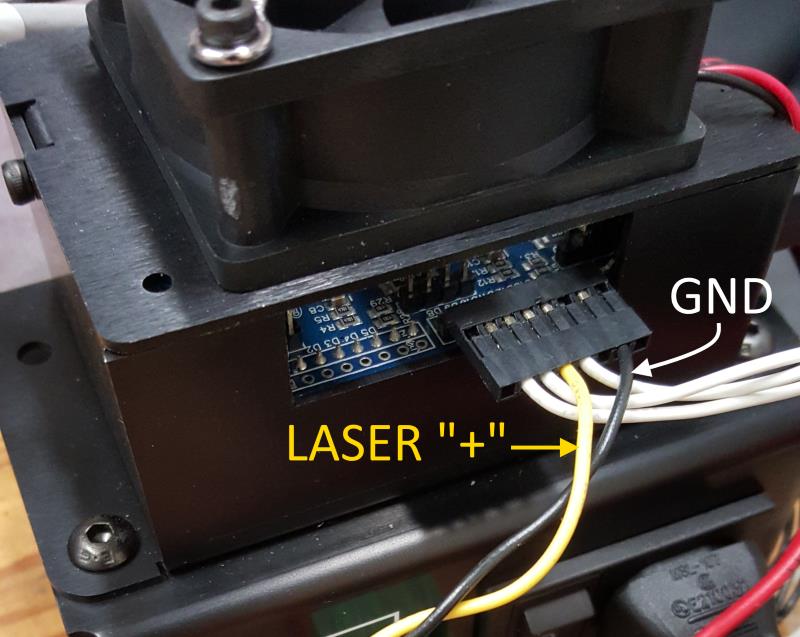
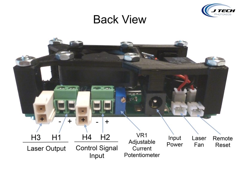
You can use the screw terminal H2 on the back of the laser driver to connect or you can buy a Molex Mini Fit Jr cable to make it cleaner and connect it to H4. We are including this cable in the Mounting kit for sale in the shop.
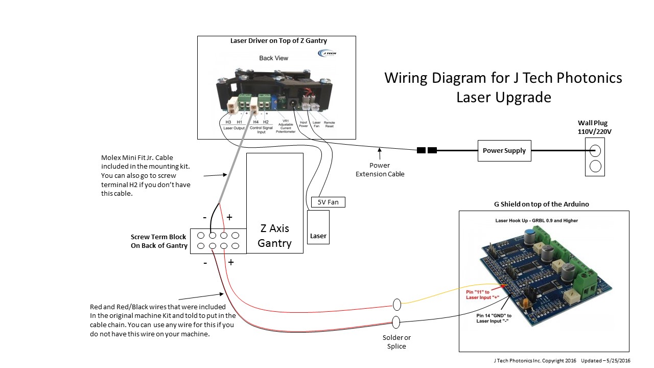
Here is the electrical wiring diagram that shows the connections from the Arduino and G Shield to the laser driver. Our X carve kit had us install the Red and Red/Black wires to the back screw terminal strip on the Z Gantry. If you do not have these wires, then use any wire to make the YELLOW and BLACK wires from your G Shield go to the laser driver.
New machine with new Controller
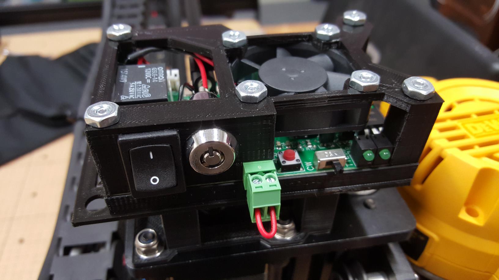
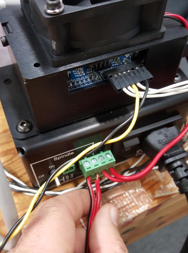
The newer machine comes standard with the new Controller and no longer has a screw terminal on the back of the Z axis gantry. This makes it super simple to connect the laser driver to the controller. Simply connect the Molex mini fit Jr. 11′ cable included in the Mounting kit from the laser driver to the Controller, routing it through the chain (or just zip tie it to the outside) all the way to the Controller connector. There are two signals you need to connect to: SPINDLE PWM and GND.
Wire the cable to the Controller:
- Red Wire (Laser + Signal) to SPINDLE PWM on controller
- Black Wire (Laser GND) to GND on X Controller
Here is the wiring diagram for the newer machine:

Laser Commands
Using the pre-loaded GRBL from Inventables
If you bought your machine with the electronics included (like most people do), then they shipped an Arduino UNO with GRBL installed already. You either have GRBL version 0.9i, 0.9j, 1.0c, or 1.1f, which is branched from the main GRBL github development site. If you just want to cut things and do black and white engraving, then you will have no problems.
To turn on and off the laser the command is:
- Laser ON: M03
- Laser OFF: M05
If you want to use power control for the laser (via Pulse Width Modulation) the laser command is:
M03 SXXXXX
Where the “XXXXX” is a number between 0 and 12000. So, some examples are:
- Laser ON 100%: M03 S12000
- Laser ON 50%: M03 S6000
- Laser ON low power: M03 S1800
- Laser OFF: M03 S0 (or M05 will work as well…)
Running the Machine
We recommend not using Easel to control your machine when using the laser. If you are using the firmware installed on your machine (the firmware that came with your machine) then you can use Easel when routing.
There are a lot of different “sender” programs that will work with your machine. In the inside of your machine is something called “GRBL” that directs how the machine moves and interprets the G Code file. The G Code file is the “instructions” and GRBL just needs some program to “send” it to the GRBL that is in the firmware of your control board.
Here is the wiki page with all of the sender program available:
http://www.shapeoko.com/wiki/index.php/Communication_/_Control
We like to use the “universal G Code sender” as it is the standard for the previous shapeoko machine and has a very large user base. It is located here:
https://github.com/winder/Universal-G-Code-Sender

If you are planning on doing pictures, then PicSender will work great to control the machine. You can get it here: PICSENDER PROGRAM
Picture Engraving Instructions
The firmware that comes with your machine will not be able to do very good picture engraving. It stops for EVERY pixel to adjust the intensity. Now, this might work if you turn your laser power on your driver really low and you are willing to wait hours for your engraving to finish but I think you might have better things to do with your time. This is why the new firmware was developed so the intensity of the laser can change without stopping for every pixel. So, in order to set up your machine for photo engraving you will need to follow a few steps. Here is the blog post on how to set up your machine:
Step By Step Upgrade Instructions
So now that you have the overview on how to complete the upgrade, lets get into the details on how to put it all together. These instructions show the 1000mm kit installation. On the 500mm machine you can either put the driver on the side of the machine or you can mount it on the Z axis. You will also probably not need the power cord extender.
Let’s get started!
STEP 1: Remove the Z motor bolts.
Make sure you have your hands below the bolts as they can fall into the X axis rails and are REALLY difficult to get out in case you drop it. Trust us, we know from experience.
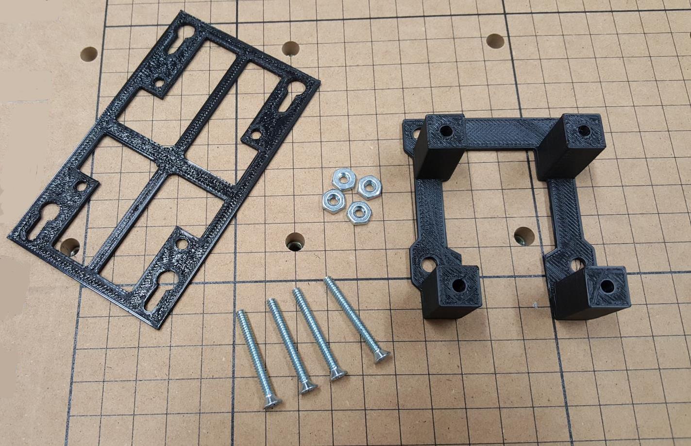
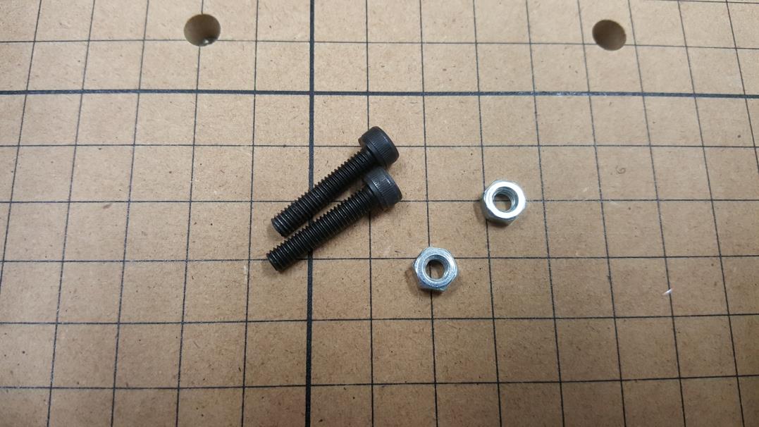
STEP 2: Get your parts ready
There should be a TOP piece and a BOTTOM mount piece, 4 x 1/32 1 1/4″ bolts and 4 nuts. (*Bolts and nuts are included in the Mounting Kit)
STEP 3: Attach BOTTOM and TOP mount pieces
Screw in the four bolts and put the nuts on as well.

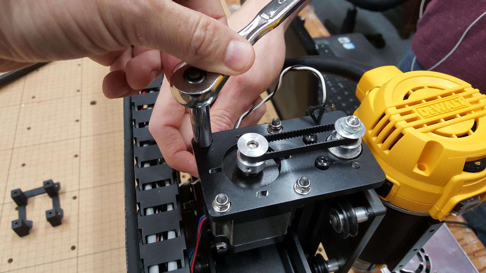
STEP 4: Place mount and use motor bolts to keep in place.
Make sure you re-tension the Z axis belt when doing this. Find something to get leverage to tension the belt and then tighten the bolt. After tension and getting the first bolt in and tightened, then finish the other three bolts.
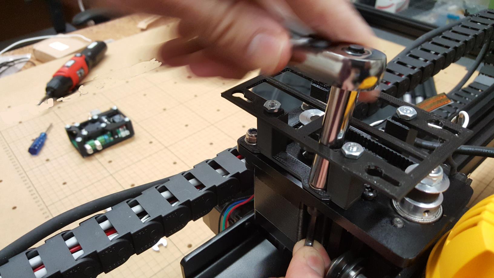
STEP 5: Loosen the screws on the laser driver.
Give just enough room so that the laser driver can “click” into the holes in the top mount.

STEP 6: Place Laser Driver on mount.
You might need to wiggle it into the correct holes and possibly turn the nuts on the bottom mount in the correct orientation for it to fit.
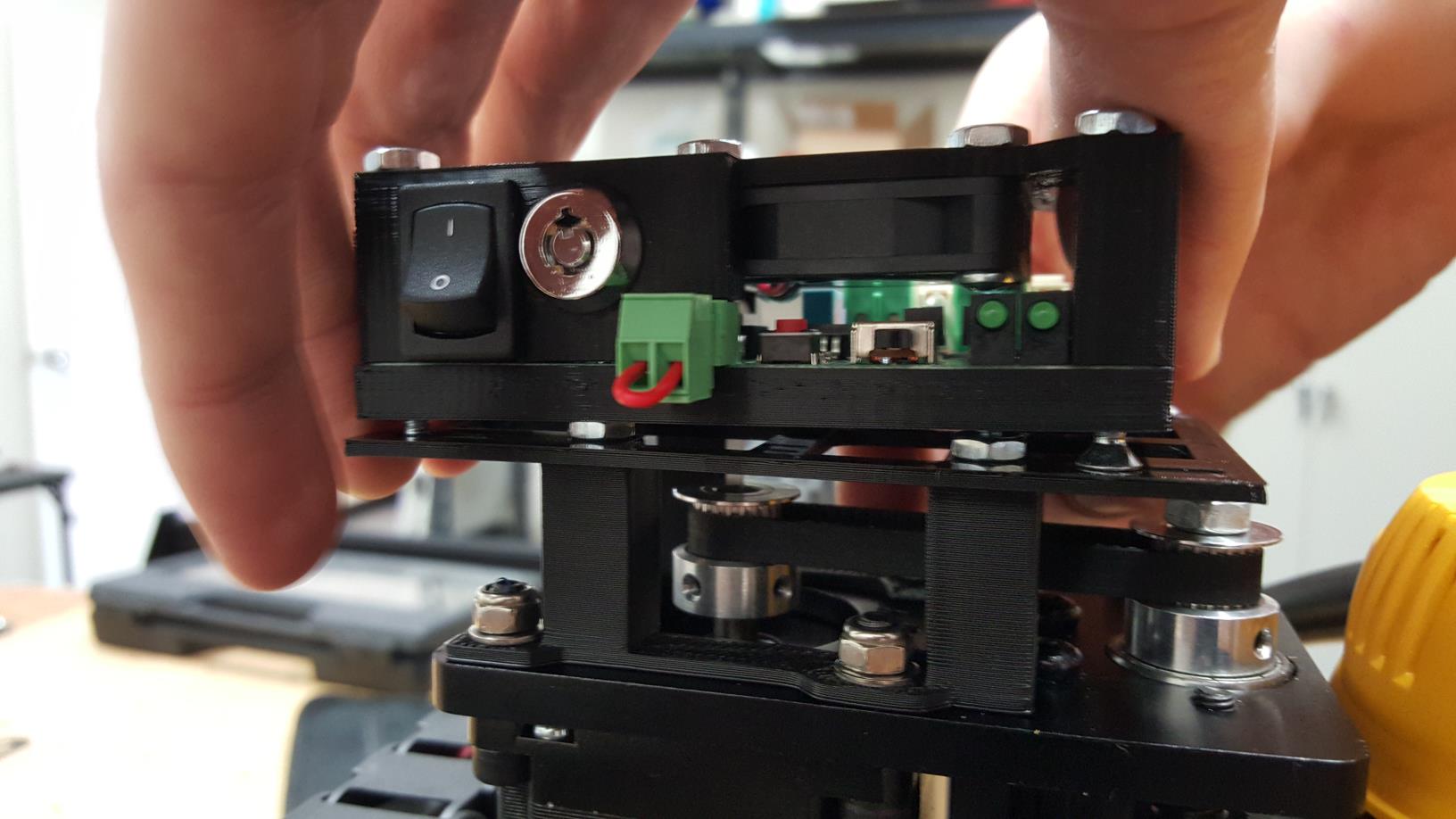
STEP 7: Lock the driver in place
You should be able to push the laser driver forward so it is sitting in the smaller cutout and firmly in place.
STEP 8: Wire the extended power cable.
This is needed on the 1000mm version and can be also on the 500mm version if your wall outlet is far from your machine. Our Mounting kit includes the extender cable shown below. If you print out your mounts then purchase it in the shop here.
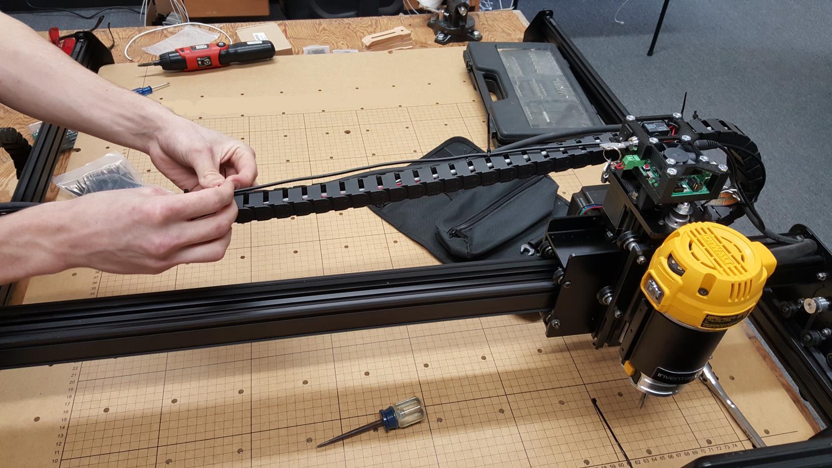
Use the provided Zip Ties in the mounting kit to attach the extender cable to the wiring chain. Plug in the cord to the laser driver and push your X stage all the way to the most positive side of your machine (to the right). Make sure you leave enough slack so it does not impede any movement of the machine. If you want, you can also put it inside the wiring chain. We already had ours put together, so this was an easier method, but does not look as good…
STEP 9: Wire the laser driver input cable.
New machine with X Controller:
There no longer is a screw terminal in the back of the gantry anymore. The cable in the mounting kit is now 11′ and can be routed all the way back to the Controller.
Wire the cable to the Controller:
- Red Wire (Laser + Signal) to SPINDLE PWM on controller
- Black Wire (Laser GND) to GND on Controller
Older Machines with Arduino and GRBL shield
We include a Molex Mini Fit Jr. cable in the Mounting kit so you can quickly disconnect the laser driver from the mount and re-connect. If you want to use the screw terminals, you can do this as well. If you are printing the mounts out yourself then you need to buy this cable from our shop.
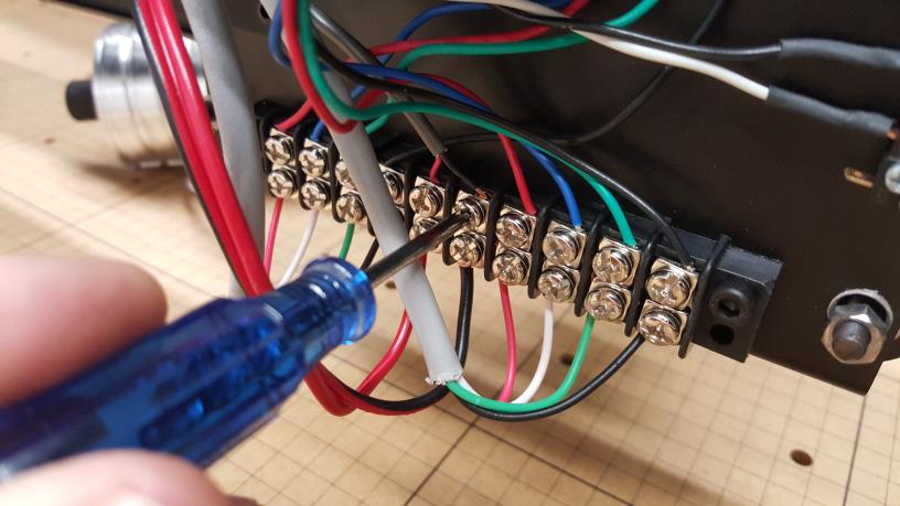
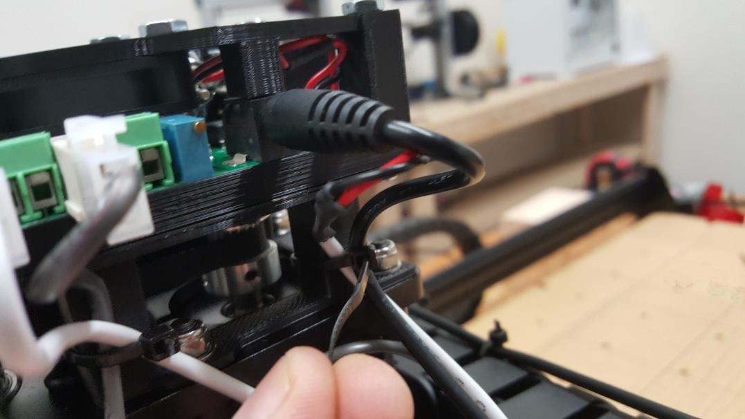
On the back of the Z axis gantry, there is the terminal block with the wires from the controller. There is a RED wire and a RED and BLACK striped wire for the SPINDLE CONTROL. In our case we do not have the 24V spindle so the other side of the terminals were not being used. Connect the laser driver input cable to the laser driver and connect the other end to the screw terminals on the back of the gantry. Here is the connection:
- Laser Driver “+” (RED WIRE) to X Carve (RED WIRE TERMINAL)
- Laser Driver “-” (BLACK WIRE) to X Carve (RED and BLACK WIRE TERMINAL)
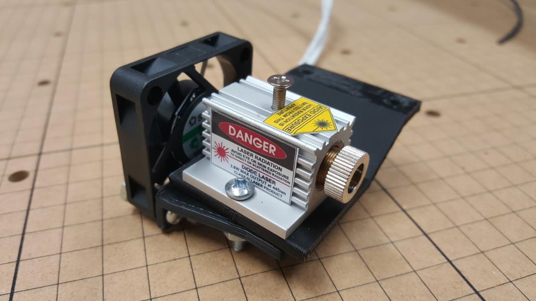
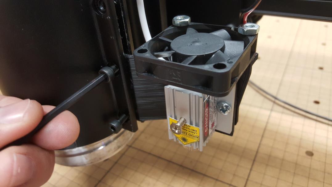
STEP 10: Attach laser to mount.
Decide whether you want to have the laser on the side of the router or in place of the router. Note, the mount we designed is for the DeWalt 611 mount that has screws on the side. If you have another mount, then you will need to figure out how to attach it to either the mount or to the back plate. The dimensions of the laser heatsink are located here for your reference.
In this picture, we are showing how to mount the laser and the laser fan upgrade for mounting on the inside of the mount (with the router removed). If you want to put it to the side next to the router, then simply attach the laser to the other side of the mount.
Here is how it looks for mounting inside the router hole:

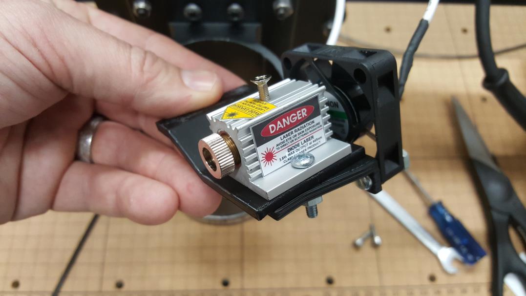
Here is how it looks if you want it on the side of the router mount:
STEP 11: Attach the laser mount to the router mount.
Use M4 x 16m (or longer) screws to attach. The Mounting kit will include these screws.
To mount INSIDE the router mount: Use the bottom two screw holes and place the laser mount between the two plates. You need to pry it open a bit to get it to fit. Put the M4 screws in the bottom two holes of the router mount.
To Mount on the OUTSIDE of the router mount: pry open the router mount slightly and place the laser mount in between the two plates in the bottom two screw location. Put the M4 screws though and tighten.
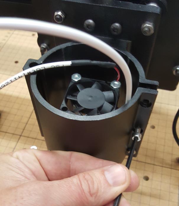
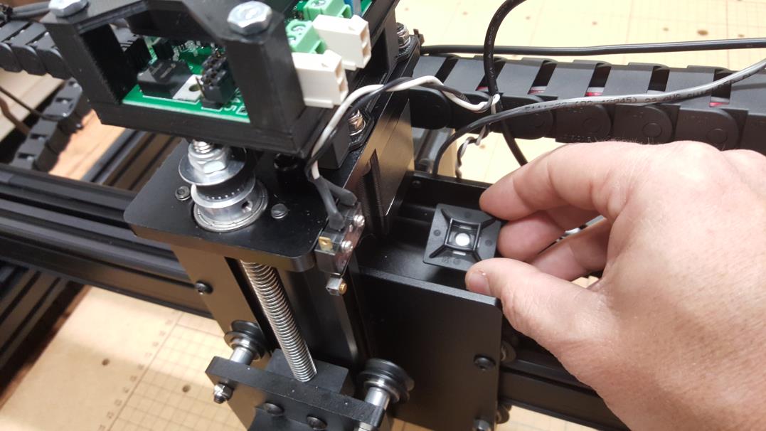
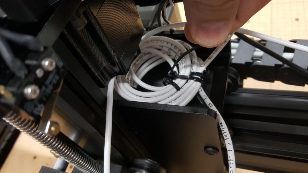
STEP 12: Clean up the laser and fan cables.
We include a little zip tie holder in the Mounting kit that can be placed on the gantry. This will be used to hold the zip ties and the extra cable from the laser and the fan. Place it in the location in the picture.
You can roll the cables up and then zip tie them down. Make sure you leave enough room for them to reach the laser driver before you put your zip tie tight.
STEP 13: Zip tie connections to the laser driver.
You want to have the cables zip tied so they can stay in the proper location for when you remove the laser driver when you are using the router. This way, when you put the laser driver back on it is easy to hook it right back up!
For the laser output and the driver input use a zip tie on the front leg of the driver mount.
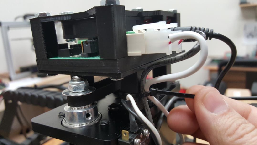
For the power, remote reset, and the laser fan use the back driver mount leg to zip tie the cables to it.
STEP 14: Wire to the Controller
New Machines
Take the Molex Mini fit cable from the Mounting kit and wire it to the Controller if you haven’t already from the previous step 9.
Wire the cable to the Controller:
- Red Wire (Laser + Signal) to SPINDLE PWM on Controller
- Black Wire (Laser GND) to GND on Controller
Older Machines: Wire the Arduino/G Shield YELLOW and BALCK wires to the RED and RED/BLACK wires.
Take the Yellow and Black wires from the Arduino and remove them from the screw terminal. Do the same for the Red and Red/Black wires.
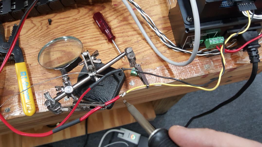
We chose to solder the wires together. You can connect them however you want, but just make sure you connect:
- Arduino Pin 11 (YELLOW WIRE) to the (RED WIRE)
- Arduino GND Pin 14 (BLACK WIRE) to the (RED and BLACK STRIPE WIRE)
You are now DONE!
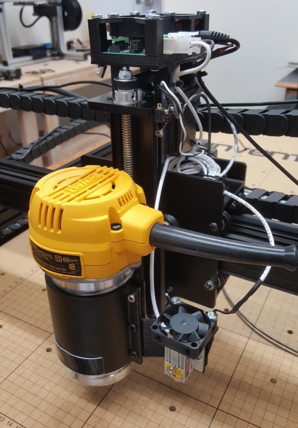
Here is what your machine should look like if you put the laser in the router holder: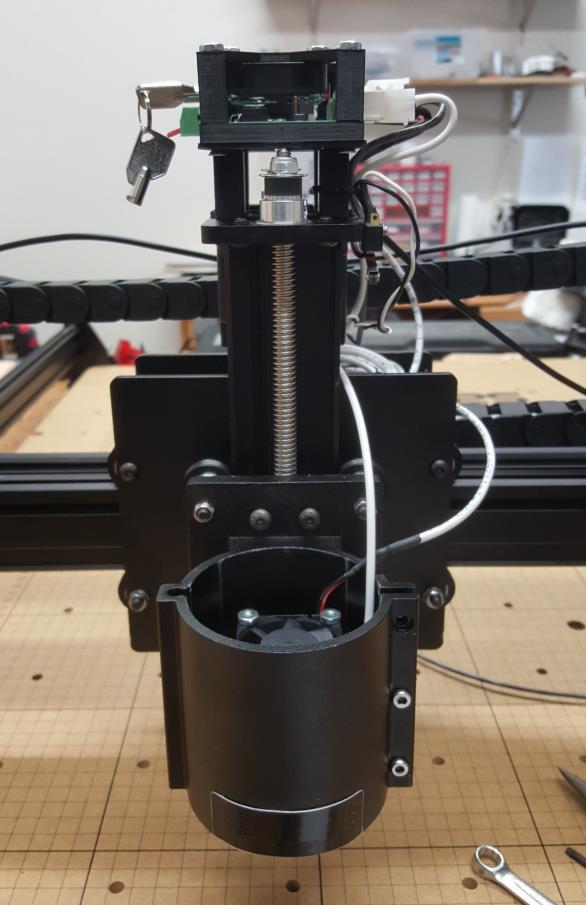
Here is what it should look like if you mount it next to the router:
Additional Upgrades:
We put a FEIN Turbo vacuum on our machine to suck the fumes out, and we mounted two lasers to our machine so we can do testing here easily with both the 2.8W laser and the 3.8W laser. You can see ours doing an image engraving in the picture. Of course you can add laser shielding to your machine for more protection!
Running your X Carve with a Laser
You can read on how to focus the machine in the following blog post here:
Make sure you have all your safety equipment and goggles on before you start your laser. Always keep a fire extinguisher available as well close by. We have not had any problems, but it is always a good idea to know where on is when using lasers.
For sender programs, we recommend using Universal G Code Sender to control your X Carve if you are not going to do any image engraving. If you are planning on doing images, then use PicSender.
You should not need to do anything to change between using your router and using your laser. Just make sure you have your laser driver turned OFF so you don’t accidentally burn something when using just the router.
So there it is! Now you are ready to start creating!
Buy your laser upgrade kit now!

Purchase Mounting Kit HERE
Remember Safety First!

We sell laser shielding to block laser radiation and reflections!
Laser Goggles are also a must!
Disclaimer
The laser used in this project is very powerful and all safety precautions must be taken. Use proper safety eyewear to prevent injury to eyes. This is a project and J Tech Photonics, Inc. is not responsible or liable for any and all damage or injury caused to people or property. The use of these instructions to make a laser cutter is under your own discretion and all safety precautions should be followed. J Tech Photonics, Inc. is not affiliated in any way with X Carve or Inventables and they may change hardware and software at any time making these instructions invalid.